


20
Dutchwest Direct Vent / Natural Vent Gas Heater
30001935
In the U.S.; Gas connection should be made in ac-
cordance with current National Fuel Gas Code, ANSI
Z223.1/NFPA 54. Since some municipalities have
additional local codes, be sure to consult your local
authority.
In Canada; consult the local authority and CSA-B149.1
installation code.
Always check for gas leaks with a mild
soap and water solution. Do not use an
open flame for leak testing.
Light the pilot according to the directions on Page 25,
before going to the next step.
Burner Information
The appliance must only use the gas specified on the
rating plate, unless converted using a Fuel Conver-
sion Kit. To convert from LP to Natural Gas use Kit
#000-5021. To convert from Natural Gas to LP use Kit
#000-5022.
Conversion instructions are provided with each kit and
beginning on Page 27 in this manual.
Air Shutter Adjustment Instructions
To adjust the air shutter, the following procedures
should be followed:
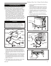
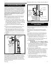
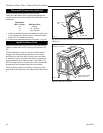
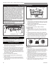
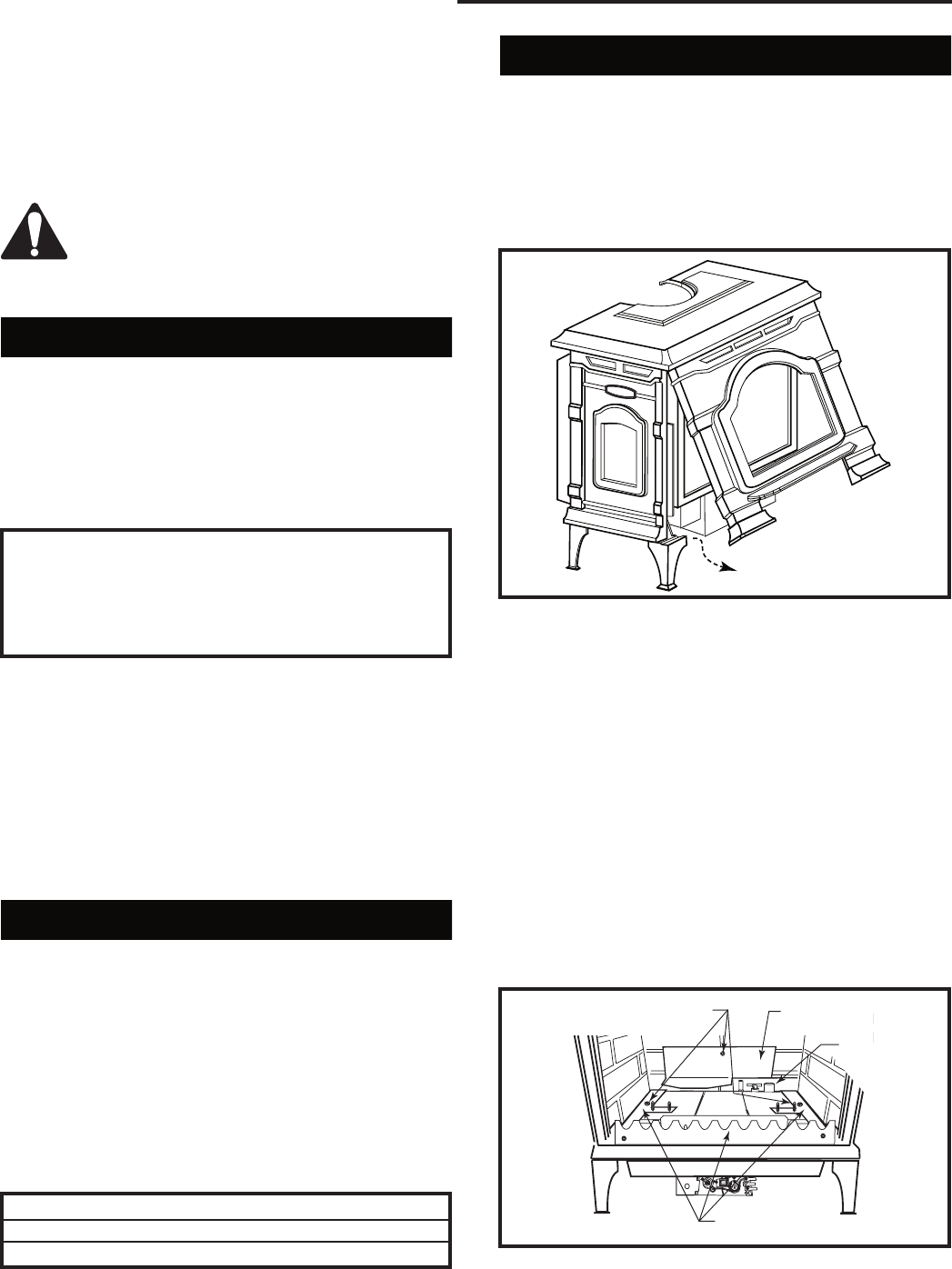
1. Remove stove front. Lift stove front up and then
swing bottom out and away to disengage from the
stove body. (Fig. 36)
2. Swing open the swiveling latches at the top left and
right corners of the glass frame. (Fig. 57, Page 31)
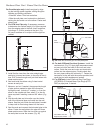
This appliance should be connected to the gas
supply only by a qualified gas service technician.
Follow all local codes.
There must be a gas shut-off between the stove
and the supply.
In order to connect Natural Gas, use a fitting with 3/8”
NPT nipple on the valve side and 1/2” natural gas sup-
ply line with an input of 28,000 BTUs at a manifold pres-
sure of 3.5” and minimum inlet supply for adjustment of
5.5” w.c.
In order to connect Propane, use a fitting with 3/8”
NPT nipple on the valve side and 1/2” propane gas
supply line with an input of 28,000 BTUs at a manifold
pressure of 10.0” and minimum inlet supply for adjust-
ment of 11.0” w.c.
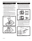
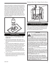
Air Shutter Adjustment
The Dutchwest is shipped from the factory with the air
shutter adjusted to the minimum allowed opening. Refer
to Table 1. Based on the altitude where the stove is
located, a shutter adjustment is acceptable to provide a
mixed balance of flame color/glow. To adjust the shutter
opening, follow the steps below.
NOTE: The air shutter may only be adjusted to a more
open position. The factory setting is the minimum allow-
able air shutter opening. (Figs. 38 & 39)
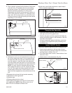
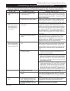
Model Natural Gas LP
Direct Vent 1/2” 1/2”
Natural Vent 1/2” 1”
Table 1. Air Shutter Adjustment
Minimum rear injector inlet openings.
D
UTCH
W
EST
D
UTCH
W
EST
Est. 1974
ST771a
DW
remove
stove front
5/30/03 djt
ST771a
Fig. 36 Remove stove front.
3. Pull the top edge of the glass and frame assembly
away from the firebox, and lift it off its supports on
the bottom of the firebox face. Place the assembly
out of the way on a flat, padded surface such as a
counter protected by a towel.
4. Take the logset out of the firebox if previously in-
stalled.
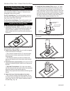
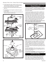
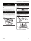
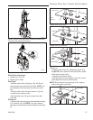
5. Remove the rear log bracket by unfastening the
screw. (Fig. 37)
6. Remove the right and left log bracket assembly by
unfastening the two screws which hold the burner in
place. (Fig. 37)
7. Hold the burner at the right hand side and lift to clear
the right burner leg. Then pull to the right to clear the
injectors on the left hand side.
ST350
Jefferson
air shutter adj
3/20/00 djt
Remove Screws
Rear Log Bracket
Pilot
Left & Right Log
Bracket Assembly
ST768
Fig. 37 Remove rear log bracket and left and right log
bracket assembly.