


18
Dutchwest Direct Vent / Natural Vent Gas Heater
30001935
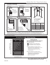
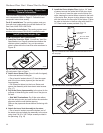
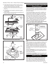
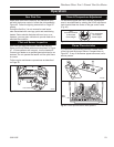
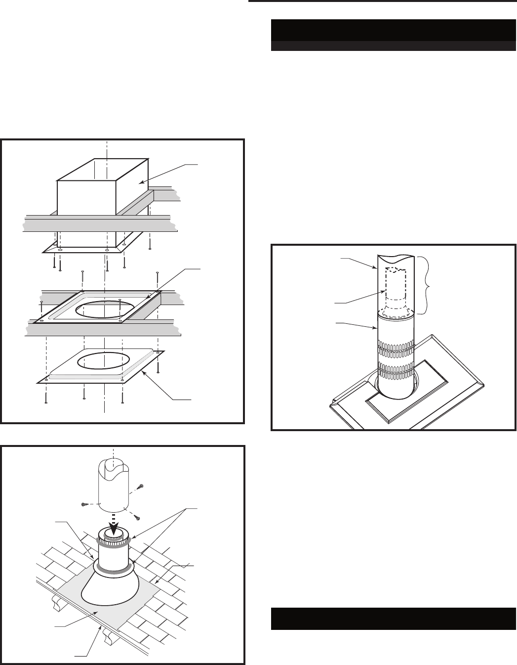
8. Install appropriate pipe sections until the vent run
reaches above the flashing. The enlarged ends of
the vent sections always face downward.
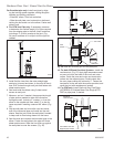
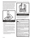
9. Install the storm collar and seal around the joints.
(Fig. 31)
10. Add additional vent lengths to achieve the proper
overall height.
11. Apply cement to the inner and outer termination col
-
lars and install the terminal cap.
ST222
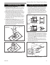
vent thru ceiling
12/99
#7DVAIS
Attic
Insulation
Shield
#7DVFS
Firestop
In Upper
Floor
#7DVFS
Firestop in
Ceiling
Use Four 8d
Nails
ST222
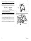
Fig. 30 Install firestops and attic insulation shield.
ST221
vent thru roof
12/99
Storm Collar
Sealant
Upper
edge of
flange goes
under upper
shingles
Flashing
#7DVSKV
(A, B of F)
Roof Support
ST221
Fig. 31 Roof support and flashing.
Venting System Assembly - Natural Vent
General Information
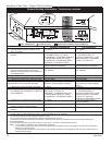
The Dutchwest Heater is shipped from the factory as
a Direct Vent Heater. It may be converted to a Natural
Vent heater by installing the Model Z31D00 FSDHAG
Draft Hood Adapter.
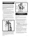
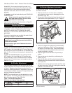
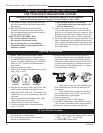
The Dutchwest Heater is approved for installation as
a Natural Vent. CFM Direct Vent pipe could be used
directly after the Draft Hood Adapter up to the ceiling,
then B-vent pipe must be used. Do not mix types of
B-vent pipe; use components from one maker or the
other. Follow the vent component maker’s instructions
exactly. The heater will also accept standard or enam-
elled 7” (150mm) diameter pipe, around the Type B
venting, for decorative purposes only. (Fig. 32)
NOTE: The restrictor plate supplied with the stove
is not used for Natural Vent applications.
ST358
DW
Decorative
pipe around b-vent
5/15/03 djt
Decorative 7”
Pipe
4” B-vent
Pipe
Draft Hood
Adapter
CFM Direct Vent
System may be
used Draft Hood
up up to the ceiling
ST766
Fig. 32 Decorative 7” pipe may be fitted around the B-vent
pipe.
The Dutchwest stove, when installed as a Natural vent
heater, includes a vent safety switch. (Fig. 60, Page
32) Operating the stove when it is not connected to a
properly installed and maintained venting system, or
tampering with or disconnecting the vent safety switch,
can result in carbon monoxide (CO) poisoning and pos-
sible death.
For U.S. installations: The venting system must con-
form with local codes and/or the current National Fuel
Gas Code, ANSI Z22.1.
For Canadian installations: The venting system must
conform to the current CSA B149.1 installation code.
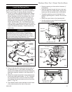
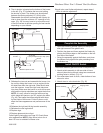
Install the Vent Pipe
Apply a bead of sealant around bottom end of inner
starter pipe (found in bag with logset) and attach to
stove. Apply a bead of sealant around top of inner
starter pipe and install the Z31D00 FSDHAG Draft
Hood according to Draft Hood instructions. (Fig. 33)