14
Dutchwest
7001135
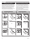
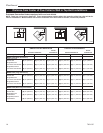
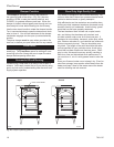
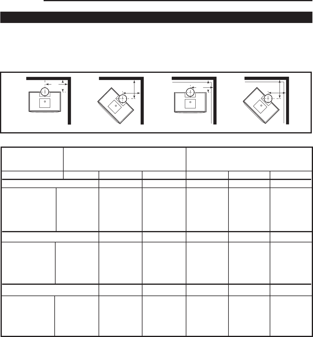
Distance from Center of Flue Collar to Wall in Top-Exit Installations
Dutchwest Convection Heaters equipped with rear heat shields
NOTE: These are not clearance distances. These measurements indicate where the centerline of the flue collar will be for
various installations. Measurements are from the centerline of the flue collar to the wall, not the wall protector.
ST427
dutchwest
flue center
line
6/30/00 djt
A
B
C
E
D
F
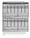
Chimney Connector Side Rear Corner Side Rear Corner
MODEL 2460 (Small Convection)
Listed, Approved
Double-wall [A] 33” (840 mm) [B] 18” (460 mm) [C] 25” (640 mm) [D] 23” (580 mm) [E] 10” (250 mm) [F] 15” (380mm)
Single Wall, with
Connector Heat Shields [A] 33” (840 mm) [B] 13” (330 mm) [C] 22” (560 mm) [D] 23” (580 mm) [E] 11” (580 mm) [F] 15” (380 mm)
Single Wall, without
Connector Heat Shields [A] 33” (840 mm) [B] 23” (580 mm) [C] 25” (640 mm) [D] 23” (580 mm) [E] 13” (330 mm) [F] 17” (430 mm)
MODEL 2461 (Large Convection)
Listed, Approved
Double-wall [A] 35” (890 mm) [B] 18” (460 mm) [C] 27” (690 mm) [D] 25” (640 mm) [E] 10” (250 mm) [F] 17” (430 mm)
Single Wall, with
Connector Heat Shields [A] 35” (890 mm) [B] 13” (330 mm) [C] 24” (610 mm) [D] 25” (640 mm) [E] 11” (280 mm) [F] 17” (430 mm)
Single Wall, without
Connector Heat Shields [A] 35” (890 mm) [B] 23” (580 mm) [C] 27” (690 mm) [D] 25” (640 mm) [E] 13” (330 mm) [F] 19” (480 mm)
MODEL 2462 (Extra-Large Convection)
Listed Approved
Double-Wall
[A] 35” (890 mm) [B] 13” (330 mm) [C] 26” (660 mm) [D] 33” (660 mm) [E] 11” (280 mm) [F] 25” (640 mm)
Single Wall, with
Heat Shields [A] 35” (890 mm) [B] 17” (430 mm) [C] 29” (740 mm) [D] 33” (840 mm) [E] 11” (280 mm) [F] 25” (640 mm)
Single Wall, without
Heat Shields [A] 35” (890 mm) [B] 22” (560 mm) [C] 33” (840 mm) [D] 33” (840 mm) [E] 17” (430 mm) [F] 27” (690 mm)
UNPROTECTED SURFACES PROTECTED SURFACES
Corner Corner
Parallel Installations Installations Parallel Installations Installations
ST427


