


61
d. Secure shield wire to CCN screw terminal
SHIELD on the COMM board.
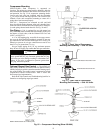
RJ14 PLUG WIRING — Units on the CCN can be monitored
from the space at the sensor through the RJ14 connector, if
desired. To wire the RJ14 connector into the CCN (Fig. 80):
1. Cut the CCN wire and strip ends of the red (+), white
(ground), and black (–) conductors. (If another wire color
scheme is used, strip ends of appropriate wires.)
2. Secure the red (+) wire to CCN screw terminal + on the
COMM board.
3. Secure the white (ground) wire to CCN screw terminal C
on the COMM board.
4. Secure the black (–) wire to CCN screw terminal – on the
COMM board.
5. Secure shield wire to CCN screw terminal SHIELD on
the COMM board.
6. Connect the other end of the communication bus cable to
the CCN communication bus.
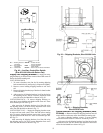
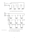
Smoke Control Modes — Rooftop units can be used
for aid in building smoke control in the event of a building fire.
The available functions include: Fire Shutdown, Pressuriza-
tion, Evacuation, and Smoke Purge. These functions are
enhanced when multiple rooftop units are used to zone a build-
ing. See Table 21 and Fig. 78 and 79.
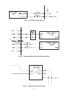
FIRE SHUTDOWN — Fire Shutdown mode terminates all
unit operation (cooling, heating, supply fan, and power
exhaust). This mode prevents recirculation of contaminated air
back into the space. The mode will not allow admission into
the space of unsuitable outside air. See Fig. 78 for wiring.
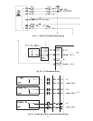
PRESSURIZATION — Pressurization mode is intended to
keep smoke out of a zone. The factory-installed optional econ-
omizer is required for this function. Pressurization is accom-
plished by the following:
• opening the economizer (option)
• running the supply fan (optional inlet guide vanes open
or optional VFD at normal duct static pressure set point)
• closing the power exhaust dampers (if installed as option
or accessory)
• shutting off the power exhaust fans (if installed as option
or accessory)
This allows the space to be overpressurized relative to adja-
cent zones and prevents or slows entry of smoke into this space
from adjacent zones. See Fig. 79 for wiring.
EVACUATION — Evacuation mode removes smoke or un-
desirable air from interior spaces without reintroducing unsuit-
able air. The factory-installed optional economizer with option/
accessory power exhaust is required for this function. Evacua-
tion is accomplished by the following:
• turning the supply fan off
• opening the economizer (option required)
• running the exhaust fans (option or accessory required)
• opening the exhaust dampers.
See Fig. 79 for wiring.
SMOKE PURGE — Smoke Purge mode removes smoke
from the interior spaces and replaces it with fresh outside air.
The factory-installed optional economizer with option/
accessory power exhaust are required for this function. Smoke
purge is accomplished by the following:
• turning supply fan on
• opening the economizer (option required)
• running the exhaust fans (option or accessory required)
• opening the exhaust dampers
See Fig. 79 for wiring.
SMOKE CONTROL INSTALLATION — Implementation of
the various smoke control modes on these units requires the in-
staller to modify the unit wiring to add contacts (via either
manual switches or relays) that will selectively interrupt and
override standard factory control sequences. See Table 21 and
Fig. 78 and 79 for more information.
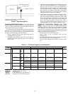
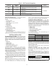
Table 21 — Smoke Control Modes
LEGEND
*Power exhaust option required for this mode.
†Applicable to VAV and PIC units with appropriate options.
IMPORTANT: A shorted CCN bus cable will prevent
some routines from running and may prevent unit from
starting. If abnormal conditions occur, unplug the connec-
tor. If conditions return to normal, check CCN connector,
and run new cable if necessary. A short in one section of
the bus can cause problems with all system elements on
the bus.
IMPORTANT: The cable selected for the RJ14 connector
wiring MUST be identical to the CCN communication bus
wire used for the entire network.
FUNCTION
MODE
Fire
Shutdown
Pressur-
ization
Evacuation*
Smoke
Purge*
Supply Fan Off On Off On
IGV/VFD† — Open/On — Open/On
Economizer Closed Open Open Open
Return Air
Damper
Open Closed Closed Closed
Exhaust
Fans
Off Off On On
Exhaust
Damper
Closed Closed Open Open
IGV — Inlet Guide Vane
PIC — Product Integrated Control
VAV — Variable Air Volume
VFD — Variable Frequency Drive
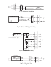
T1
T2
1
24
3
5
6
7
8
9
10
12
13
14
15
16
TH
C
SN
T56- SPTT55- SPT
UNIT
TB202
11
R
Y1 Y2 W1 W2 G
R
Y1 Y2 W1 W2 G
FIELD SUPPLIED THERMOSTAT
RC
1
65432
TB203
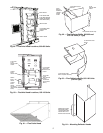
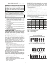
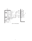
Fig. 67 — Field Control Thermostat Wiring
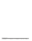
Fig. 68 — T55 or T56 Wiring