


59
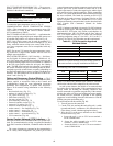
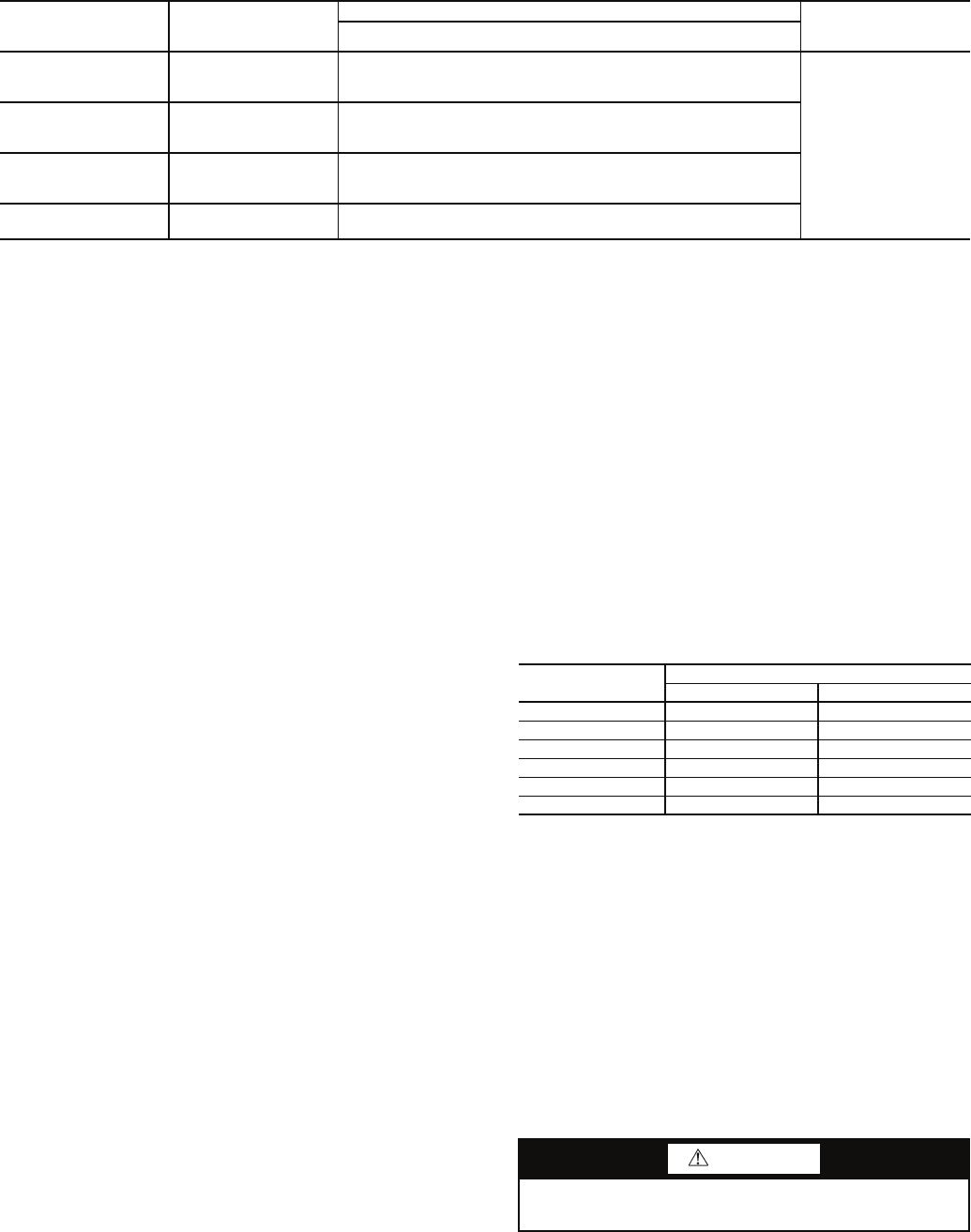
Table 19 — SGC Thermistor Designations
SGC — Staged Gas Controller
Install Unit Accessories — For applications requiring
accessories, the following packages are available:
All units:
• barometric relief
• space temperature sensor
•CO
2
sensor
• space temperature sensor with CO
2
• airflow switch
• filter switch
• smoke detector
All 48ZG,ZT,Z6 units:
• modulating power exhaust
• pressure operated unloaders
All 48ZN,ZW,Z8 units:
• modulating power exhaust
• VFD remote display
Refer to the individual accessory installation instructions in
each accessory package for information on installing accessories.
CONTROLS INSTALLATION
Constant Volume (CV) Units —
The 48ZG,ZT,Z6 units
may be used in applications with additional control features,
options, or accessories. Refer to the appropriate accessory
installation instructions for more information on installing that
accessory. Control options and accessories available for CV
units are:
• thermostats
• enthalpy sensor
• enthalpy switch
• relative humidity sensor
• CEM (controls expansion module)
• Navigator™ hand-held display
CONTROL WIRING — The unit can be controlled with a
Carrier-approved accessory electro-mechanical or electronic
thermostat that has two stages of cooling, two stages of heating
control, and an output for fan control. The thermostat may also
include time of day scheduling or use scheduling routines built
into the ComfortLink™ controls.
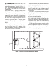
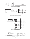
Install the thermostat according to the installation instruc-
tions shipped with the accessory thermostat. Locate thermostat
assembly on a solid interior wall to sense average temperature.
Route thermostat cable or equivalent leads of colored wire
from subbase terminals through conduit into the low voltage
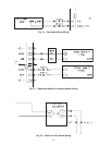
connections in the main control box. For thermostat TB203
connections, see Fig. 67.
NOTE: For wire runs up to 50 ft, use no. 18 AWG (American
Wire Gage) insulated wire (35 C minimum). For over 75 ft, use
no. 14 AWG insulated wire (35 C minimum). All wire larger
than no. 18 AWG cannot be directly connected at the thermostat
and will require a junction box and splice at the thermostat.
Variable Air Volume (VAV) Units — The 48ZN,
ZW, Z8 units may be used in applications with additional con-
trol features, options, or accessories. Refer to the appropriate
accessory installation instructions for more information on in-
stalling that accessory. Refer to the Controls and Troubleshoot-
ing manual for more information concerning installation and
configuration of options and accessories. Control options and
accessories available for VAV units are:
• enthalpy sensor
• enthalpy switch
• relative humidity sensor
• CEM (controls expansion module)
• Navigator hand-held display
• VFD remote display
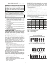
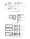
VAV CONTROL WIRING — The recommended types of
control wiring are shown below:
SENSORS — Sensors should be wired using single twisted
pairs of 20 AWG (American Wire Gage) conductor cable rated
for the application, except for the T-56 accessory sensor which
requires 3-conductor cable.
NOTE: Humidity and CO
2
sensors must be powered from
isolated 24-v power supplies.
HUMIDITY CONTROL AND HOT WATER AND
STEAM VALVES — These devices require 20 AWG twisted
pair conductor cables rated for the application for the 4 to
20 mA signal.
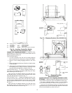
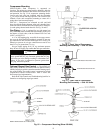
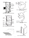
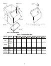
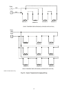
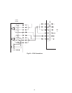
SPACE TEMPERATURE SENSOR (T-55) — The space tem-
perature sensor (P/N 33ZCT55SPT) is shipped standard with
every unit, and is located in the main control box. Space tem-
perature sensor wires are to be connected to terminals in the
unit main control box.
To connect the space temperature sensor, see Fig. 68.
THERMISTOR
PIN
CONNECTION
POINT
FUNCTION AND LOCATION
PART NO.
Thermistors
SAT1 J8 – 1,2 (SGC)
Supply-Air Thermistor (SAT) — Inserted into supply section
underneath the gas heat section (factory-provided,
field-installed)
HH79NZ033
SAT2 J8 – 3,4 (SGC)
Supply-Air Thermistor (SAT) — Inserted into supply section
underneath the gas heat section (factory-provided,
field-installed)
SAT3 J8 – 5,6 (SGC)
Supply-Air Thermistor (SAT) — Inserted into supply section
underneath the gas heat section (factory-provided,
field-installed)
LIMTTEMP J8 – 15,16 (SGC)
Limit Switch Thermistor (LIMTTEMP) — Inserted next the
lower limit switch (factory-installed)
MANUFACTURER
PART NO.
Regular Wiring Plenum Wiring
Alpha 1895 —
American A21451 A48301
Belden 8205 884421
Columbia D6451 —
Manhattan M13402 M64430
Quabik 6130 —
CAUTION
Jumper MUST be in place between pins 1 and 3, 3 and 4
or inaccurate readings could result.