


51
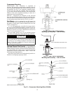
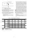
Air Pressure Tubing — Before options such as inlet
guide vanes (IGV), variable frequency drive (VFD), and/or
modulating power exhaust can operate properly, the pneumatic
tubing for pressure sensing must be installed. Use fire-retardant
plenum tubing (field-supplied). All control devices use
1
/
4
-in.
tubing. Tubing must be run from the appropriate sensing loca-
tion (in the duct or in the building space) to the control device
location in the unit.
INLET GUIDE VANES — The tubing for the duct pressure
(DP) control option should sample supply duct pressure about
2
/
3
of the way out from the unit in the main trunk duct, at a
location where a constant duct pressure is desired.
The duct pressure is sensed by a pressure transducer. The
output of the pressure transducer is directed to the unit control
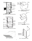
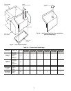
module. On all sizes, the DP transducer is located in the unit
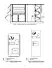
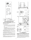
auxiliary control box. See Fig. 45 and 46 for auxiliary control
box location. See Fig. 47 and 48 for auxiliary control box
details. Use a nominal
1
/
4
-in. plastic tubing.
VARIABLE FREQUENCY DRIVE — The tubing for the
duct pressure (DP) control option should sample supply duct
pressure about
2
/
3
of the way out from the unit in the main
trunk duct, at a location where a constant duct pressure is
desired.
On these units, the duct pressure is sensed by a pressure
transducer. The pressure transducer output is directed to the unit
control module. On all sizes, the DP transducer is located in the
unit auxiliary control box. See Fig. 45 and 46 for auxiliary
control box location. See Fig. 47 and 48 for auxiliary control
box details. Use a nominal
1
/
4
-in. plastic tubing.
Refer to appropriate base unit Controls and Troubleshooting
book for instructions on adjusting set points for duct pressure
controls.
MODULATING POWER EXHAUST — The tubing for the
building pressure (BP) control (achieved via the modulating
power exhaust option) should sample building pressure in the
area near the entrance lobby (or other appropriate and sensitive
location) so that location is controlled as closely to design pres-
sures as possible.
These units use a pressure transducer for sensing building
pressure. The BP transducer is located in the unit auxiliary con-
trol box. See Fig. 45 and 46 for auxiliary control box location.
See Fig. 47 and 48 for auxiliary control box details. Use a nom-
inal
1
/
4
-in. plastic tubing.
For instructions on adjusting BP control set points, refer to
the Controls and Troubleshooting book.
RETURN/EXHAUST POWER EXHAUST — The tubing
for the building pressure (BP) control (achieved via the return/
exhaust power exhaust option) should sample building pres-
sure in the area near the entrance lobby (or other appropriate
and sensitive location) so that location is controlled as closely
to design pressures as possible.
The units use a pressure transducer for sensing building
pressure. The BP transducer is located in the unit auxiliary con-
trol box. See Fig. 46 for auxiliary control box location. Fig. 49
for auxiliary control box details. Use a nominal
1
/
4
-in. plastic
tubing.
For instructions on adjusting BP control set points, refer to
the Controls and Troubleshooting book.
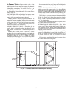
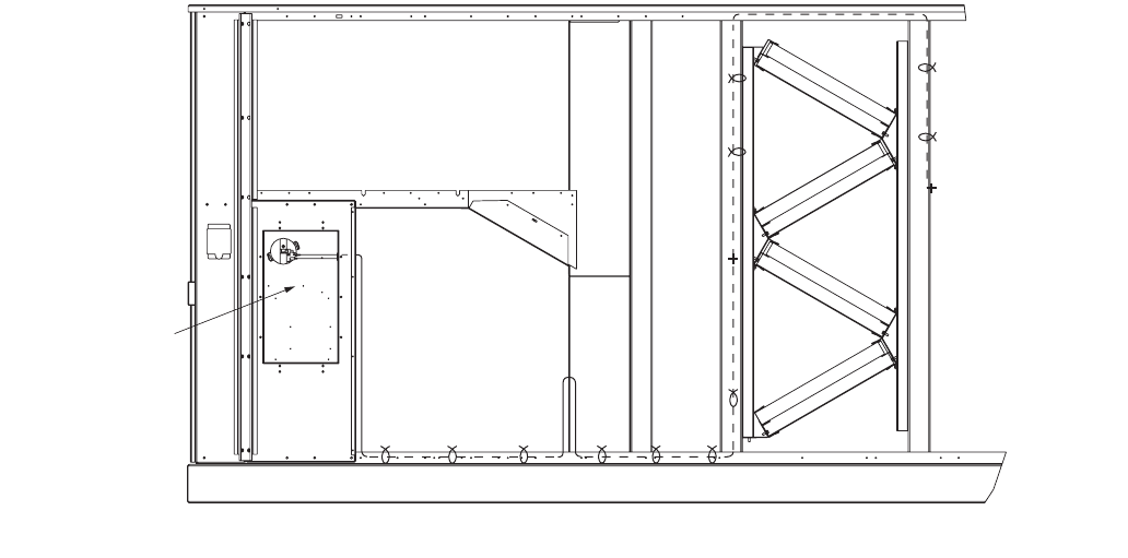
AUXILIARY
CONTROL
BOX
Fig. 45 — Auxiliary Control Box Location (Sizes 030-050)