74
c. Secure the black (–) wire to CCN screw terminal –
on the COMM board.
d. Secure shield wire to CCN screw terminal
SHIELD on the COMM board.
Optional UPC Open Installation
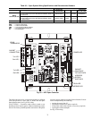
WIRING THE UPC OPEN TO THE MS/TP NET-
WORK — The UPC Open controller communicates using
BACnet on an MS/TP network segment communications at
9600 bps, 19.2 kbps, 38.4 kbps, or 76.8 kbps.
Wire the controllers on an MS/TP network segment in a dai-
sy-chain configuration. Wire specifications for the cable are
22 AWG (American Wire Gage) or 24 AWG, low-capacitance,
twisted, stranded, shielded copper wire. The maximum length
is 2000 ft.
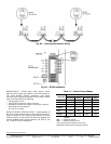
Install a BT485 terminator on the first and last controller on
a network segment to add bias and prevent signal distortions
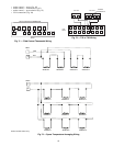
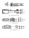
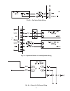
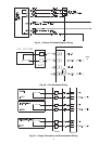
due to echoing. See Fig. 85-87.
To wire the UPC Open controller to the BAS network:
1. Pull the screw terminal connector from the controller's
BAS Port.
2. Check the communications wiring for shorts and
grounds.
3. Connect the communications wiring to the BAS port’s
screw terminals labeled Net +, Net -, and Shield.
NOTE: Use the same polarity throughout the network
segment.
4. Insert the power screw terminal connector into the UPC
Open controller's power terminals if they are not current-
ly connected.
5. Verify communication with the network by viewing a
module status report. To perform a module status report
using the BACview keypad/display unit, press and hold
the “FN” key then press the “.” Key.
To install a BT485 terminator, push the BT485 on to the
BT485 connector located near the BACnet connector.
NOTE: The BT485 terminator has no polarity associated with
it.
To order a BT485 terminator, consult Commercial Products
i-Vu® Open Control System Master Prices.
MS/TP WIRING RECOMMENDATIONS — Recommen-
dations are shown in Tables 29 and 30. The wire jacket and UL
temperature rating specifications list two acceptable alterna-
tives. The Halar specification has a higher temperature rating
and a tougher outer jacket than the SmokeGard specification,
and it is appropriate for use in applications where the user is
concerned about abrasion. The Halar jacket is also less likely to
crack in extremely low temperatures.
NOTE: Use the specified type of wire and cable for maximum
signal integrity.
Smoke Control Modes — Rooftop units can be used
for aid in building smoke control in the event of a building fire.
The available functions include: Fire Shutdown, Pressuriza-
tion, Evacuation, and Smoke Purge. These functions are
enhanced when multiple rooftop units are used to zone a build-
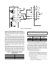
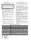
ing. See Table 31 and Fig. 82 and 83.
FIRE SHUTDOWN — Fire Shutdown mode terminates all
unit operation (cooling, heating, supply fan, and power
exhaust). This mode prevents recirculation of contaminated air
back into the space. The mode will not allow admission into
the space of unsuitable outside air. See Fig. 82 for wiring.
PRESSURIZATION — Pressurization mode is intended to
keep smoke out of a zone. The factory-installed optional econ-
omizer is required for this function. Pressurization is accom-
plished by the following:
• opening the economizer (option)
• running the supply fan (optional inlet guide vanes open
or optional VFD at normal duct static pressure set point)
• closing the power exhaust dampers (if installed as option
or accessory)
• shutting off the power exhaust fans (if installed as option
or accessory)
Table 29 — MS/TP Wiring Recommendations
LEGEND
IMPORTANT: A shorted CCN bus cable will prevent
some routines from running and may prevent unit from
starting. If abnormal conditions occur, unplug the connec-
tor. If conditions return to normal, check CCN connector,
and run new cable if necessary. A short in one section of
the bus can cause problems with all system elements on
the bus.
SPECIFICATION RECOMMMENDATION
Cable Single twisted pair, low capacitance, CL2P, 22 AWG (7x30), TC foam FEP, plenum rated cable
Conductor 22 or 24 AWG stranded copper (tin plated)
Insulation Foamed FEP 0.015 in. (0.381 mm) wall 0.060 in. (1.524 mm) O.D.
Color Code Black/White
Twist Lay 2 in. (50.8 mm) lay on pair 6 twists/foot (20 twists/meter) nominal
Shielding Aluminum/Mylar shield with 24 AWG TC drain wire
Jacket
SmokeGard Jacket (SmokeGard PVC) 0.021 in. (0.5334 mm) wall 0.175 in. (4.445 mm) O.D.
Halar Jacket (E-CTFE) 0.010 in. (0.254 mm) wall 0.144 in. (3.6576 mm) O.D.
DC Resistance 15.2 Ohms/1000 feet (50 Ohms/km) nominal
Capacitance 12.5 pF/ft (41 pF/meter) nominal conductor to conductor
Characteristic Impedance 100 Ohms nominal
Weight 12 lb/1000 feet (17.9 kg/km)
UL Temperature Rating
SmokeGard 167°F (75°C)
Halar -40 to 302°F (-40 to 150°C)
Voltage 300 Vac, power limited
Listing UL: NEC CL2P, or better
AWG — American Wire Gage
CL2P — Class 2 Plenum Cable
DC — Direct Current
FEP — Fluorinated Ethylene Polymer
NEC — National Electrical Code
O.D. — Outside Diameter
TC — Tinned Copper
UL — Underwriters Laboratories


