


7
MAINTENANCE
Cleaning Procedure —
Notify the proper authorities
that the smoke detector system is undergoing maintenance, and
that the system will temporarily be out of service. Disable the
zone or system undergoing maintenance to prevent unwanted
alarms and possible dispatch of the fire department.
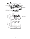
AIR FILTERS
1. Turn off power to the system.
2. Remove and inspect sampling tube filters.
3. If filters are heavily coated with dirt, replace them with
new filters. If they are not heavily coated, use a vacuum
cleaner or compressed air nozzle to remove dust, then
reinstall the filters.
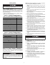
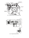
PHOTO DETECTOR BOARD
1. Remove the screen by gently grasping on each side and
pulling straight off.
2. Lift the photo chamber in the same fashion. Vacuum the
screen and cover. Use clean, compressed air to loosen and
blow out any remaining debris.
3. Vacuum photo chamber, then use clean compressed air to
blow area clean.
4. Replace the chamber by pressing it onto the base. Press
the screen into place. It should fit tightly on the chamber.
Filter Replacement —
The filters do not substantially
affect smoke detector performance even when up to 90% of the
filter is clogged. Quarterly visual inspection usually suffices to
determine whether the filters should be replaced. Only a high
percentage of contamination affects performance. If further
testing is required, compare differential pressure readings with
and without the filters installed. If the difference exceeds 10%,
then replace the filters. The pressure differential should never
fall below 0.0015 in. wg.
Board Replacement
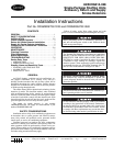
SMOKE DETECTOR BOARD REPLACEMENT
1. Remove the two detector board mounting screws.
2. Pull gently on the board to remove it.
3. To replace the board, align the board mounting features,
holes, and the interconnect terminals. Push the board into
place.
4. Secure board with the two mounting screws.
POWER BOARD REPLACEMENT
1. Disconnect wiring from the terminal block.
2. Remove the two power board mounting screws.
3. Pull gently on the board to remove it.
4. To replace the board, align the board mounting features,
holes, and the interconnect terminals. Push the board into
place.
5. Secure board with the two mounting screws.
6. Re-connect wiring to terminal block.
TROUBLESHOOTING
Test and maintain unit smoke detectors as recommended
in NFPA 72. Before conducting these tests, notify the proper
authorities that the smoke detection system will be temporarily
out of service. Disable the system under test to prevent unwant-
ed alarms.
Smoke Entry Tests
AIRFLOW TEST — The smoke detector is designed to oper-
ate over an extended air speed range of 100 to 4000 fpm. To
verify sufficient sampling of unit air, turn on the 48/50HG unit
indoor fan using the Service Test function (see Controls and
Troubleshooting Guide for details on Service Test) and use a
manometer to measure the differential pressure between the
two sampling tubes.
The differential pressure should measure at least
0.0015 in. wg and no more than 1.2 in. wg. Because most com-
mercially available manometers cannot accurately measure
very low pressure differentials, applications with less than
500 fpm of unit air speed may require the use of a current-
sourcing pressure transmitter or the use of aerosol smoke (see
Smoke Response Test below).
SMOKE RESPONSE TEST — Drill a
1
/
4
-in. hole 3-ft
upstream from the unit smoke detector. Use the Service Test
function (see Controls and Troubleshooting Guide for details
on Service Test) to turn on the 48/50HG unit indoor fan.
Measure the air velocity with an anemometer. Air speed must
be at least 100 fpm. If the air speed is greater than 500 fpm, use
a conventional manometer to measure differential pressure be-
tween the sampling tubes.
Spray aerosol smoke into the unit through the
1
/
4
-in. hole
for 5 seconds. Wait two minutes for the unit smoke detector to
alarm. If the unit smoke detector alarms, then air is flowing
through the detector. Remove the unit smoke detector cover
and blow out the residual aerosol smoke from the chamber and
reset the unit smoke detector. Use duct tape to seal the aerosol
smoke entry hole.
To determine if smoke is capable of entering the sensing
chamber, visually identify any obstructions. Plug the exhaust
and inlet tube holes to prevent unit air from carrying smoke
away from the detector head, then blow smoke directly at the
head to cause an alarm.
Remove the plugs after this test, or the smoke detector will
not function properly and damage may result.