


2
INSTALLATION
Check Package Contents —
Remove accessory pack-
aging and inspect shipment for damage. If any damage is
found, file a claim with the shipping agent immediately. If any
item is missing or any part does not assemble properly, notify
your Carrier distributor.
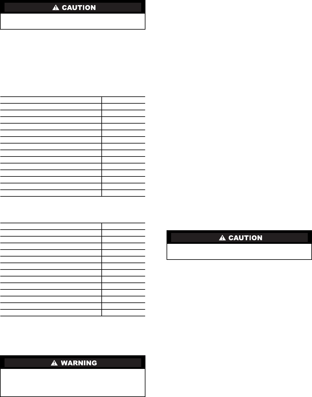
Tables 1A and B list the accessory package contents.
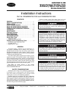
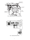
Figure 1 shows the smoke detector.
Table 1A — Accessory Package Contents —
Return Air Smoke Detector (CRSMKDET001C00)
Table 1B — Accessory Package Contents —
Supply Air Smoke Detector (CRSMKSUP001A00)
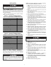
Return Air Smoke Detector Installation —
The return air smoke detector is to be installed in the predrilled
holes located above compressor B1 in the electrical/
compressor section (Fig. 2).
NOTE: For horizontal applications it is easiest to install the
smoke detector prior to making duct connections.
1. Open the hinged electrical/compressor access door and
secure.
2. Find the 2 plugs located above compressor B1, remove
and discard. Cut holes in the insulation located behind the
partition.
3. Remove cover from smoke detector. The screws will
remain captured in the cover.
4. Place foam gaskets over each sampling tube on smoke
detector. (See Fig. 1.)
5. Remove one knockout from top of smoke detector.
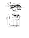
6. Insert stripped ends of wire harness through knockout and
wire to smoke detector as shown in Fig. 3.
7. Provide strain relief for wires by attaching wire tie to
ground screw located next to the knockout in the smoke
detector. Tighten the wire tie.
8. Slide smoke detector into holes in partition with the
terminal block to the right. Do not secure at this time.
9. Slide sampling tube into left-hand hole of smoke detector.
It might be necessary to tilt the smoke detector upwards
in order properly align the sampling tube.
10. Remove the unit side panel at the return end of the unit.
Save screws for use later.
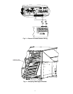
11. Mount the sampling tube support bracket to the cross
member with two
1
/
4
AB-14
5
/
8
-in. screws as shown
in Fig. 4. Insert large snap bushing into hole in bracket.
12. Slide sampling tube into bracket, making sure that the
sampling holes point down. Pull the sampling tube so that
it is flush with the smoke detector.
13. Return to Electrical/Compressor section and secure sam-
pling tube to smoke detector with two no. 6 self-tapping
screws.
14. Attach smoke detector to partition using two, 8-18
3
/
4
-in.
pan head screws.
15. Return to side panel and insert tube end plug into
sampling tube.
16. Replace the unit side panel.
17. Return to Electrical/Compressor section and insert
sampling tube filters into both sampling tube holders.
(See Fig. 1.)
18. Install the snap bushing in the center knockout under-
neath the control terminal strips located in the bottom
right-hand corner of the control box.
19. Feed wires through snap bushing and connect to appro-
priate terminals as shown in Fig. 3.
20. Restore power to the unit.
21. Configure ComfortLink™ controller as specified in
Configuring the ComfortLink Controller on page 5.
22. Perform Standby, Alarm, and Sensitivity Tests on page 7.
At a minimum, the Magnet test should be performed to
verify smoke detector wiring.
23. Replace smoke detector cover.
24. Check for alarms. Correct any problems.
When installing the smoke detector in the unit, follow all
local codes. Damage to unit may result.
ITEM QUANTITY
Smoke Detector with Cover
1
Sampling Tube (long)
1
Sampling Tube Filters
2
Test Magnet
1
Foam Gaskets
2
Screw, no. 6 Self Tapping
2
Tube End Plug (large)
1
Sampling Tube Support Bracket
1
Screw, 8-18
3
/
4
-in. Pan Head
2
Screw,
1
/
4
AB-14
5
/
8
-in.
2
Small Snap Bushing
1
Large Snap Bushing
1
Harness Assembly (4-Wires, short)
1
Wire Tie, Screw Mounted
1
ITEM QUANTITY
Smoke Detector with Cover
1
Sampling Tube (short)
1
Sampling Tube Filters
2
Test Magnet
1
Foam Gaskets
2
Tube End Plug (small)
1
Screw, 8-18
3
/
4
-in. Pan Head
2
Small Snap Bushing
1
Harness Assembly (4-Wires, long)
1
Wire Tie, Screw Mounted
5
Wire Tie
1
Screw, no. 8 Self Tapping
1
Screw, no. 10
2
Prior to installation of this accessory, make sure all power
is disconnected to the unit and locked out. Failure to dis-
connect power supply prior to servicing may result in seri-
ous injury.
Do not overtighten the screws. Damage to smoke detector
may result.