


9. Loosen setscrew holding blower wheel on motor shaft.
10. Remove bolts holding motor mount to blower housing and
slide motor and mount out of housing. Disconnect ground wire
attached to blower housing before removing motor.
11. Lubricate motor (when oil ports are provided).
a. Remove dust caps or plugs from oil ports located at each
end of motor.
b. Use a good grade of SAE 20 nondetergent motor oil and
put 1 teaspoon, 5 cc, 3/16 oz, or 16 to 25 drops in each oil
port. Do not over-oil.
c. Allow time for total quantity of oil to be absorbed by each
bearing.
d. Wipe excess oil from motor housing.
e. Replace dust caps or plugs on oil ports.
12. Remove blower wheel from housing.
a. Mark cutoff location to ensure proper reassembly.
b. Remove screws holding cutoff plate and remove cutoff
plate from housing.
c. Lift blower wheel from housing through opening.
13. Clean blower wheel and motor using a vacuum cleaner with
soft brush attachment. Do not remove or disturb balance
weights (clips) on blower wheel blades. The blower wheel
should not be dropped or bent as balance will be affected.
14. Reinstall blower wheel by reversing items 12 a through c. Be
sure wheel is positioned for proper rotation.
15. Reassemble motor and blower by reversing items 5 through
10. If motor has ground wire, be sure it is connected as before.
Be sure the motor is properly positioned in the blower
housing. The motor oil ports must be at a minimum of 45°
above the horizontal centerline of the motor after the blower
assembly has been reinstalled in the furnace.
16. Reinstall blower assembly in furnace.
17. Reinstall control. Connect blower electrical leads to control.
Please note that the common wire connection is 3/16 in. and
all other wire connections are 1/4 in. for assembly. DO NOT
FORCE.
18. Reconnect wires to auxiliary limit switch on blower housing
(downflow/horizontal furnace only).
19. Reinstall vent pipe and enclosure (downflow/horizontal fur-
nace only).
20. Turn on electrical power and check for proper rotation and
speed changes between heating and cooling.
21. Replace blower access door. Secure with 2 screws
(downflow/horizontal furnace only).
CLEANING HEAT EXCHANGER
The following steps should be performed by a qualified service
technician.
NOTE: Deposits of soot and carbon indicate the existence of a
problem which needs to be corrected. Take action to correct the
problem.
If it becomes necessary to clean the heat exchanger because of
carbon deposits, soot, etc., proceed as follows:
1. Turn off gas and electrical power to furnace.
2. Remove 2 screws from front of blower access door
(downflow/horizontal furnace only) and remove control and
blower access doors.
3. Remove vent pipe enclosure (downflow/horizontal furnace
only) and disconnect vent pipe from relief box.
4. Remove 2 screws that secure relief box. (See Fig. 6 or 7.)
5. Disconnect wires to the following components.
a. Draft safeguard switch
b. Inducer motor
c. Pressure switch
d. Limit overtemperature switch(es)
e. Gas valve
f. Hot surface ignitor
g. Flame-sensing electrode
h. Two wiring connectors leading to control
6. Remove 8 screws that secure flue collector box to center
panel. Be careful not to damage sealant.
7. Remove complete inducer assembly from furnace, exposing
flue openings.
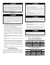
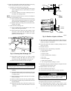
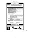
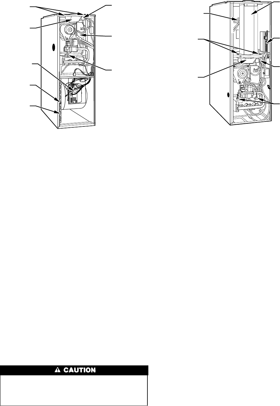
Fig. 6—Model 58PAV Upflow
A92063
DRAFT
SAFEGUARD
SWITCH
FLUE
COLLECTOR
BOX
MANUAL
RESET LIMIT
SWITCH
MOUNTING
SCREWS
RELIEF
BOX
CONTROL
BOARD
FILTER
RETAINER
WASHABLE
FILTER
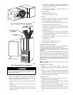
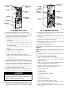
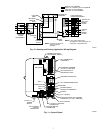
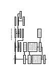
Fig. 7—Model 58RAV Downflow
A92064
VENT PIPE
ENCLOSURE
CONTROL
BOARD
DRAFT
SAFEGUARD
SWITCH
MANUAL
RESET LIMIT
SWITCHES
AUXILIARY
LIMIT
SWITCH
(WHEN USED)
MOUNTING
SCREWS
RELIEF
BOX
4