


1. Leave 115-v power to furnace turned on.
2. Remove main furnace door.
3. Look into blower access panel sight glass for current LED
status.
NOTE: Leave blower access panel installed to maintain power to
control center to view current LED status.
4. BRIEFLY remove either wire from the main limit switch until
the LED goes out, then reconnect it.
Make sure limit switch wire does not contact any metallic
component such as the gas valve. If wire is shorted, 3-amp
fuse on control center will blow.
NOTE: If wire to main limit is disconnected longer than 4 sec, the
control senses limit circuit is open. Main blower will start and
retrieval request will be ignored.
5. When above items have been completed, the component test
sequence will occur as described in the Component Test
Sequence section above.
NOTE: Be sure to record the status code which is flashed 4 times
at start of component test for further troubleshooting.
6. After component test is completed and LED is ON continu-
ously indicating the furnace is ready to operate when a signal
from the thermostat is received, replace main furnace door.
INITIATING COMPONENT TEST AND RETRIEVING STA-
TUS CODE BY JUMPERING CONTROL TEST TERMINAL
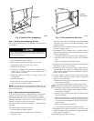
1. Remove main furnace door.
2. Remove blower access panel.
3. Manually close blower access panel door switch. Use a piece
of tape to hold switch closed.
Blower access panel door switch opens 115-v power to
control center. No component operation can occur. Caution
must be taken when manually closing this switch for service
purposes. Failure to follow this warning could result in
electrical shock, personal injury, or death.
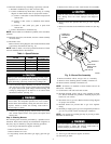
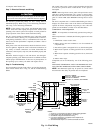
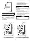
4. BRIEFLY short (jumper) TEST, 1/4-in. quick-connect termi-
nal on control center (adjacent to the LED diagnostic light)
and the C
OM terminal on thermostat connection block. (See
Fig. 12.)
NOTE: If TEST to C
OM terminals are jumpered longer than 2 sec,
LED will flash rapidly, and retrieval request will be ignored.
5. When above items have been completed, the component test
sequence will occur as described in the Component Test
Sequence section above.
NOTE: Be sure to record the status code which is flashed 4 times
at start of component test for further troubleshooting.
6. After component test is completed and furnace is operating
properly, release blower access panel door switch, replace
blower access panel, and replace main furnace door.
Step 9—Checking Heat Tape Operation (If Applicable)
In applications where the ambient temperature around the furnace
is 32°F or lower, freeze protection measures are required. If this
application is where heat tape has been applied, check to ensure it
will operate when low temperatures are present.
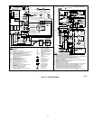
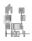
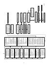
Fig. 12—Control Center
A93052
G
R
Y
W
3-AMP FUSE
Com
24V
HUMIDIFIER TERMINAL
(24-VAC 0.5 AMP MAX)
LED OPERATION &
STATUS LIGHT
HARNESS CONNECTOR
24V TRANSFORMER SEC-2
SPARE 1
SPARE 2
EAC 1 (BLACK)
EAC-ELECTRONIC AIR CLEANER
TERMINALS (115-VAC 1.5 AMP MAX)
EAC 2 (WHITE)
115-VAC (L2) NEUTRAL
CONNECTION
24V THERMOSTAT
TERMINALS
BLOWER SPEED
SELECTION TERMINALS
INDUCER MOTOR
CONNECTOR
115-VAC (L1)
POWER
SUPPLY
HOT SURFACE
IGNITOR
CONNECTOR
HEAT
COOL
BLOWER OFF DELAY
ADJUSTMENT SWITCH
SEC-1
TEST/TWIN
HUM
9