


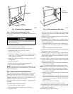
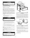
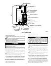


11. Reinstall condensate trap and tubing if previously removed.
a. Reinstall condensate trap in hole in blower shelf.
b. Connect condensate trap drain tubes. See Fig. 8 or tubing
diagram on main furnace door for proper tube location.
(1.) Connect 1 tube (blue or blue and white striped) from
collector box.
(2.) Connect 1 tube (violet or unmarked) from inducer
housing.
(3.) Connect 1 tube (relief port, green or pink) from
collector box.
c. Connect field drain to condensate trap.
NOTE: Ensure tubes are not kinked or pinched, as this will affect
operation.
12. Reinstall control box, transformer, and door switch assembly
on blower shelf.
13. Reconnect wires.
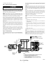
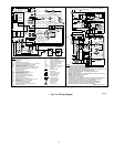
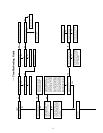
Refer to furnace wiring diagram, and connect thermostat leads
if previously disconnected. (See Fig. 15.)
NOTE: Refer to Table 1 for motor speed lead relocation if leads
were not identified before disconnection.
Heating speed selection MUST be adjusted to provide proper
temperature rise as specified on the rating plate. Failure to
adjust the heating speed may shorten heat exchanger life.
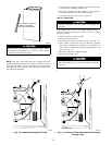
14. Turn on electrical supply. Manually close blower access panel
door switch. Use a piece of tape to hold switch closed. Check
for proper rotation and speed changes between heating and
cooling by jumpering R to G and R to Y on control center
thermostat terminals. (See Fig. 12.)
Blower access panel door switch opens 115-v power to
control center. No component operation can occur. Caution
must be taken when manually closing this switch for service
purposes. Failure to follow this warning could result in
personal injury or death.
15. If furnace is operating properly, release blower access panel
door switch, replace blower access panel, and replace main
furnace door.
Step 3—Cleaning Burners
The following items should be performed by a qualified service
technician. If the burners develop an accumulation of light dirt or
dust, they may be cleaned by using the following procedure:
1. Turn off gas and electrical supplies to furnace.
2. Remove main furnace door.
3. Remove burner box cover.
4. Using backup wrench, disconnect gas supply pipe from gas
valve.
5. Remove wires from gas valve. Note location for reassembly.
Label all wires prior to disconnection when servicing con-
trols. Wiring errors can cause improper and dangerous
operation.
6. Remove burner box pressure tube from gas valve regulator
fitting.
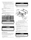
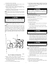
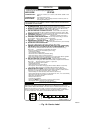
7. Remove screws that secure manifold to burner box. (See Fig.
5.)
8. Remove manifold, orifices, and gas valve as 1 assembly.
9. Remove screws attaching burner assembly in burner box.
10. Remove burner assembly from burner box.
NOTE: All burners are attached to burner bracket and can be
removed as 1 assembly.
11. Clean burners with soft brush and vacuum.
12. Reinstall manifold, orifice, and gas valve assembly in burner
box. Ensure manifold seal grommet is installed properly and
burners fit over orifices.
13. Reconnect wires to gas valve. Refer to furnace wiring diagram
for proper wire location.
14. Reinstall burner box pressure tube to gas valve regulator
fitting.
15. Reinstall gas supply pipe to gas valve using backup wrench on
gas valve to prevent rotation and improper orientation.
NOTE: Use propane gas resistant pipe dope to prevent gas leaks.
DO NOT use Teflon tape.
Gas valve switch or knob MUST be facing forward or tilted
upward. Failure to follow this warning could result in
property damage, personal injury, or death.
16. Replace burner box cover.
17. Turn on gas and electrical supplies to furnace.
18. Check for gas leaks.
Table 1—Speed Selector
COLOR SPEED
FACTORY
ATTACHED TO
Black High Cool
Yellow (When Present) Medium High Spare
Blue Medium Low Heat
Red Low Spare
White Common Com
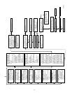
Fig. 5—Burner Box Assembly
A93295
MANIFOLD
MOUNTING
SCREW
MANIFOLD
GAS VALVE
REGULATOR
FITTING
GAS VALVE
4