


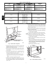
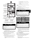

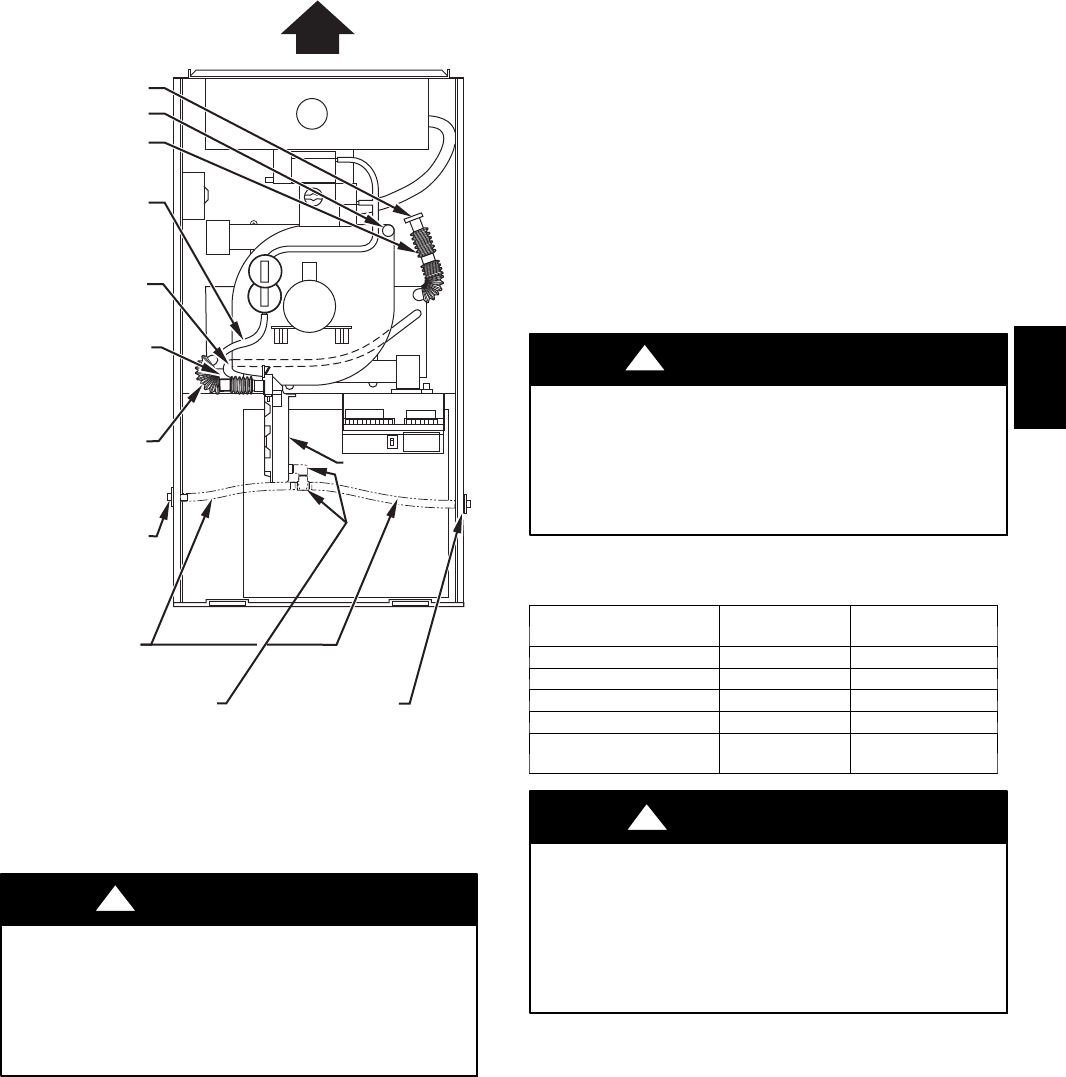
5
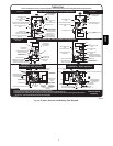
COLLECTOR BOX
TUBE (PINK)
COLLECTOR BOX
TUBE (GREEN)
INDUCER HOUSING
(MOLDED) DRAIN
TUBE (BEHIND
COLLECTOR BOX
DRAIN TUBE)
COLLECTOR BOX
DRAIN TUBE (BLUE)
FIELD-INSTALLED
FACTORY-SUPPLIED
DRAIN TUBE
COUPLING (LEFT
DRAIN OPTION)
FIELD-INSTALLED
FACTORY-SUPPLIED
DRAIN TUBE
FIELD-INSTALLED
FACTORY-SUPPLIED
1
⁄
2
-IN. CPVC STREET
ELBOWS (2) FOR
LEFT DRAIN OPTION
FIELD-INSTALLED
FACTORY-SUPPLIED
DRAIN TUBE
COUPLING (RIGHT
DRAIN OPTION)
CAP
COLLECTOR BOX
DRAIN TUBE (BLUE
& WHITE STRIPED)
PLUG
CONDENSATE
TRAP
A01030
Fig. 5 -- Factory-- Shipped Upflow Tube Configuration
(Shown with Blower Access Panel Removed)
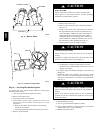
UNIT DAMAGE HAZARD
Failure to follow this caution may result in noise or furnace
component failure.
The blower wheel should not be dropped or bent as balance
will be affected.
CAUTION
!
g. Clean wheel per instructions on degreaser cleaner. Do
not get degreaser in motor.
9. Reassemble motor and blower wheel by reversing items 8b
through 8f. Ensure wheel is positioned for proper rotation.
Tighten setscrew to between 140 --160 in.--lb torque.
NOTE: Be sure to attach ground wire to blower housing.
10. Reinstall blower assembly in furnace.
11. Reinstall control box, transformer, and door switch as-
sembly on blower shelf.
12. Reinstall condensate trap and tubing if previously removed.
a. Reinstall condensate trap in hole in blower shelf.
b. Connect condensate trap drain tubes. See Fig. 5 or
tubing diagram on main furnace door for proper tube
location.
(1.) Connect 1 tube (blue or blue and white striped)
from collector box.
(2.) Connect 1 tube (violet or unmarked) from inducer
housing.
(3.) Connect 1 tube (relief port, green or pink) fro m
collector box.
NOTE: Ensure tubes are not kinked or pinched, as this will affect
operation.
c. Connect field drain to condensate trap.
13. Reconnect wires.
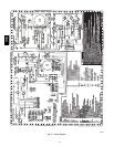
Refer to furnace wiring diagram and connect thermostat leads if
previously disconnected. (See Fig. 16.)
NOTE: R efer to Table 3 for motor speed lead reconnection if
leads were not identified before disconnection.
UNIT DAMAGE HAZARD
Failure follow this caution may result in unit component
damage.
Heating air speed selection MUST be adjusted to provide
proper temperature rise as specified on the rating plate.
CAUTION
!
Ta ble 3 – Speed Selection
COLOR SPEED
FACTORY
ATTACHED TO
Gray 5 Cool
Yellow 4 Spare
Blue 3 High---Heat
Orange 2 Spare
Red 1
Low Heat/Cont
Fan
ELECTRICAL SHOCK HAZARD
Failure to follow this warning could result in personal injury
or death.
Blower access door switch opens 115-- v power to furnace
control. No component operation can occur. Caution must be
taken when manually closing this switch for service purposes.
!
WARNING
14. Turn on electrical supply. Manually close blower access
door switch. Use a piece of tape to hold switch closed.
Check for proper rotation and speed changes by performing
a component self--test as shown at the bottom of Service la-
bel. (See Fig. 21.)
15. If furnace is operating properly , remove tape to release
blower access door switch, replace blower access door, and
replace main furnace door.
Step3—CleaningBurners
The following items should be performed by a qualified service
technician. If the burners develop an accumulation of light dirt or
dust, they may be cleaned by using the following procedure:
1. Turn off gas and electrical supplies to furnace.
2. Remove main furnace door.
3. Remove burner box cover.
4. Using backup wrench, disconnect gas supply pipe from fur-
nace gas control valve.
58MEC