


13
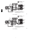
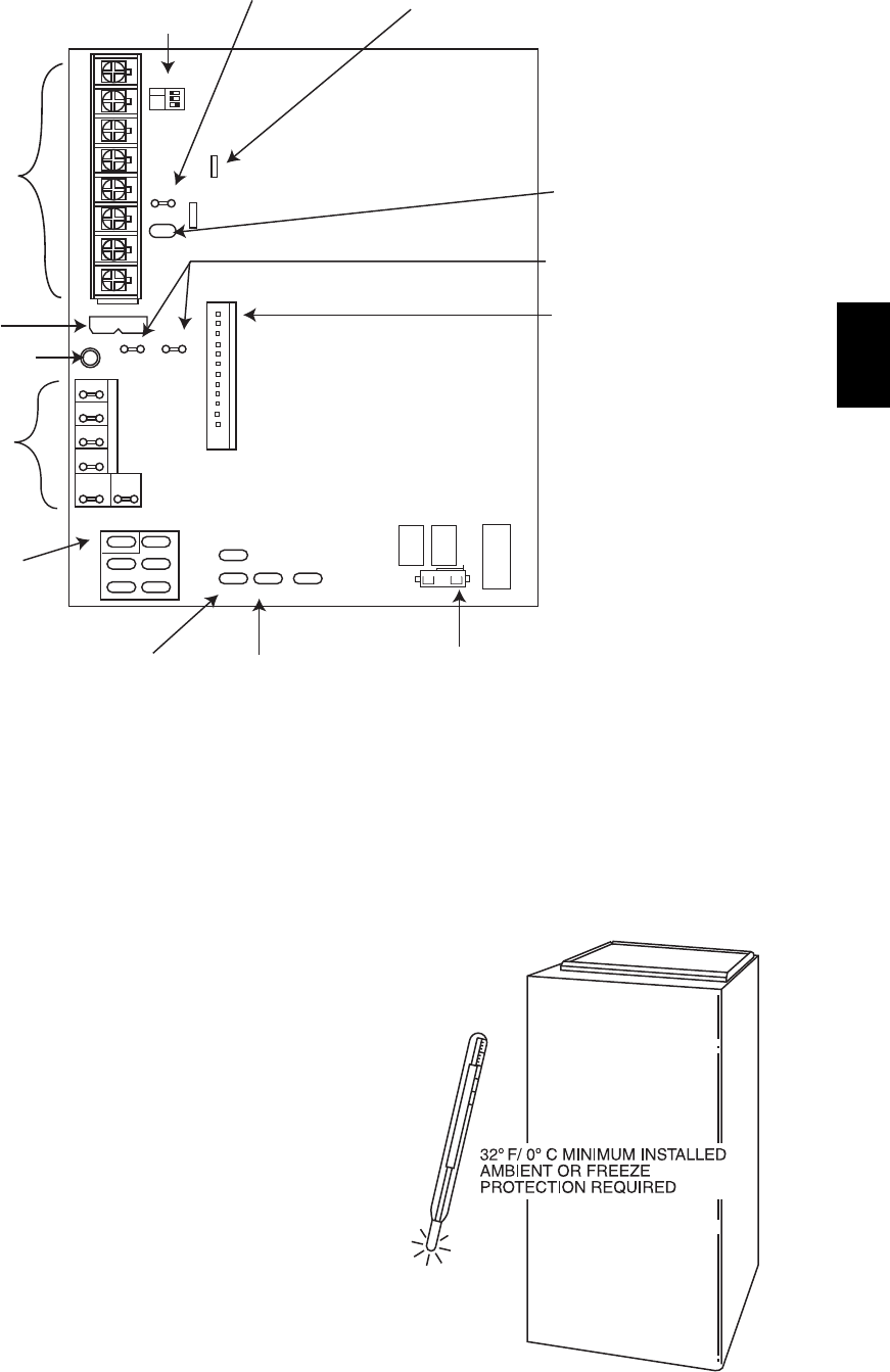
TEST / TWIN
HUM
PLT
SEC-2 SEC-1
COM 24VAC
PL1
W2 Y DHUM G COM W/W1 Y/Y2 R
24V
FUSE 3-AMP
EAC-2
EAC-1
L1 BL-1 PR-1
L2
COM
HIHT
COOL
LO HT
SPARE 2 SPARE 1
24V MTR
TAPS
BLOWER SPEED
TERMINALS
115-VAC (L2)
NEUTRAL
CONNECTIONS
LED OPERATION
& DIAGNOSTIC LIGHT
3-AMP FUSE
24-V THERMOSTAT
TERMINALS
SET UP SWITCHES
LOW HEAT ONLY
AND BLOWER
OFF-DELAY
TWINNING AND/OR
COMPONENT TEST
TERMINAL
ACRDJ - AIR CONDITIONING
RELAY DISABLE JUMPER
HUMIDIFIER TERMINAL
(24 VAC 0.5 AMPS MAX)
TRANSFORMER
24 VAC CONNECTIONS
PL1-LOW VOLTAGE
MAIN HARNESS CONNECTOR
PL2 - HOT SURFACE
IGNITER/INDUCER
MOTOR CONNECTION
115 VAC
BLOWER POWER (BL1)
CONNECTION
115 VAC LINE (L1)
CONNECTION
LHT
OFF
DLY
ON
OFF
1 2 3
IDR
HSIR
IDM
IHI/LOR
PL2
1
HSI HI LO
1
A08344
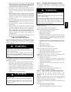
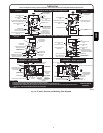
Fig. 17 -- Two--Stage Control
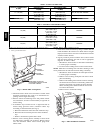
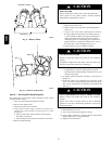
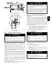
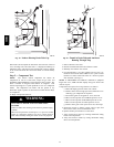
5. Insert funnel in tube and pour up to 1 quart of antifreeze,
propylene glycol (RV, swimming pool antifreeze, or equi-
valent) into funnel until it is visible at point where condens-
ate enters open drain. (See Fig. 20.)
6. Reconnect drain cap to inducer housing.
7. Replace main furnace door.
8. Propylene glycol need not be removed before restarting fur-
nace.
WIRING DIAGRAM
See Fig. 22 for Wiring Diagram.
TROUBLESHOOTING
Use the Troubleshooting Guide, the status code LED on the
control and the Component Test to isolate furnace operation
problems.
Step 1 — Status Codes
For an explanation of status codes, refer to service label located on
back of main furnace door or Fig. 21. The stored status codes will
NOT be erased from the control memory, if 115-or 24-v power is
interrupted. The control will store up to 7 Status Codes.
NOTE: Removing the blower access door will open the blower
access door switch and terminate 115--v power to the control. To
read current status code, remove main furnace door. The status
code LED can be viewed through the sight glass on the blower
access door.
NOTE: NO thermostat signals may be present at control and all
blower off delays must be completed to view previous codes.
To retrieve previous codes, remove one of the red main limit or
flame rollout switch wires 1 to 4 sec until the LED light goes out,
the reconnect it. (Do not leave red wire disconnected for longer
periods of time as the control will assume an overtemperature
condition exists and will respond with blower operation.) This
places the control in the status recall mode and displays the first
code stored in memory.
A07911
Fig. 18 -- Winterizing the Furnace
58MEC