


8
WALL THERMOSTAT INSTALLATION
The following instructions apply to RC and RP units
only.
NOTE: Carrier thermostats are recommended. See
Accessories section.
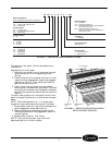
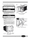
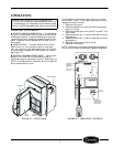
■ THERMOSTAT WIRE ROUTING — Thermostat
wire is field supplied. Recommended wire gage is 18 to
20 gage solid thermostat wire. Thermostat wire should
always be routed around or under, NEVER through,
the wall sleeve. The wire should then be routed behind
the front panel to the easily accessible terminal con-
nector. See Figures 14 and 15.
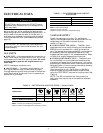
■ INSTALL THERMOSTAT — All remote control
units.
1. Check to be sure power to unit is disconnected.
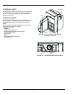
2. Pull terminal connector to remove.
NOTE: Terminal connector can be removed and re-
placed to simplify thermostat wiring.
3. Connect wires from terminals on the thermostat
to terminals on chassis terminal board connector.
See Figures 15 and 16.
4. Reinstall terminal connector.
5. Restore power to unit.
NOTE: Refer to thermostat installation instructions
for details on installing thermostat.
NOTE: Fan speed is user-selectable from the control
panel on the unit.
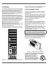
IMPORTANT: Only trained, qualified personnel
and service mechanics should install electrical
accessories on Carrier 52C and 52P series products
per Carrier’s installation instructions. Please con-
tact your local electrical contractor, dealer, or dis-
tributor for assistance.
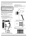
R
G
Y
W
O
C
TYPICAL
WALL
THERMOSTAT
R
G
Y
W
O
C
TERMINAL
BLOCK
SEE
NOTE #1
SEE
NOTE #2
FIGURE 15 — TERMINAL CONNECTOR
REMOVAL AND REPLACEMENT
NOTES:
1. Use terminal “O” for heat pump connection only.
2. Terminal C (common) is typically only required for digital thermostats.
3. See table below for terminal descriptions.
FIGURE 16 — WIRING CONNECTIONS
TERMINAL DESIGNATION
R 24 VAC
G Fan
Y Compressor
W Electric Heat
O Reversing Valve
C Common
POWER
CORD
THERMOSTAT
FAN SPEED
SELECTOR
SWITCH
FAN SPEED
HI
LO
R
G
Y
W
O
C
TERMINAL
CONNECTOR
THERMOSTAT
WIRE (FIELD
SUPPLIED)
FIGURE 14 — CONTROL BOX TERMINAL
CONNECTOR FOR WALL THERMOSTAT MODELS