


7
■ INSTALL CHASSIS IN SLEEVE (See Figures 11 to
13)
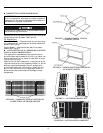
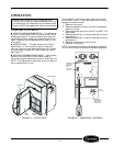
1. Inspect foam gaskets (top, bottom, both sides) on
chassis. Replace foam gaskets if torn or missing.
2. If retrofitting into a GE, Amana, Trane, or
Friedrich wall sleeve/grille, remove any existing
foam seals from competitive manufacturer’s grille
before installing unit.
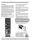
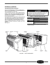
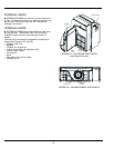
3. Remove shipping tape from vent door. See Figure 11.
4. Carefully remove power cord packing material
and discard.
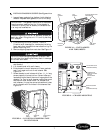
5. Lift chassis level with wall sleeve.
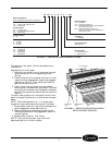
6. Slide chassis into wall sleeve until foam gaskets
rest firmly against front of wall sleeve. See
Figure 12.
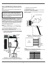
7. Screw chassis to wall sleeve with four 1
3
/
4
-in. long
screws taped to the control box. Screw holes are
located on both sides of the mounting angles of the
chassis. For Carrier wall sleeves, use the top-most
and bottom-most screw holes. For competitive
wall sleeves, line up the correct attachment holes
on the chassis with the holes in the sleeves. See
Figure 13.
IMPORTANT: The gaskets combine with the sleeve
face to create a weather barrier. If the chassis is
installed in a non-Carrier sleeve, this weather bar-
rier may not be effective.
Chassis weighs up to 150 lb. For personal protection,
seek help when lifting the unit. Lift unit by holding
unit basepan.
Failure to remove shipping tape will prevent fresh
air vent door from opening and may result in damage
to the vent door cable.
BOTTOM SCREW
HOLE
(CARRIER SLEEVE)
TOP SCREW HOLE
(CARRIER SLEEVE)
COMPETITIVE
MANUFACTURER
SLEEVE
ATTACHMENT
HOLES
TOP
GASKET
SIDE
GASKET
BOTTOM
GASKET
COIL TUBE
SHEETS
FACTORY-INSTALLED
FOAM SEALS
FIGURE 12 — UNIT GASKETS
AND TUBE SHEETS
FIGURE 13 — CHASSIS MOUNTING
VENT
DOOR
SHIPPING
TAPE
VENT DOOR
CABLE
FIGURE 11 — LOCATION OF SHIPPING TAPE
ON VENT DOOR