


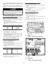
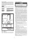

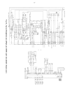

Economizer Motor — All control of the motor (i.e.,
enthalpy changeover, minimum position control and mixed
air control) is accomplished from the main unit microproces-
sor through a relay board. Service and installation instruc-
tions for the unit should be consulted to verify proper op-
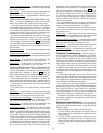
eration of thesecontrols. The economizermotor may be checked
out separately. See Fig. 52 for VAV economizer motor con-
nection information.
Motor Test
Apply 24 volt AC power to terminals T1 and T2 of
motor. Connections to motor terminals 2 and 3 must be
disconnected
A Motor Test A Expected Result and Response
Jumper 1 to Motor drives open; if not,
2 at motor replace motor.
B Motor Test B Expected Result and Response
Jumper 1 to Motor drives closed; if not,
3 at motor replace motor.
Variable Frequency Drive
Factory-installed optional VFD is located near the sup-
ply fan and motor. During any service work or pro-
gramming at the VFD, operation of the fan and motor
is not desirable. Either disable the supply fan or install
an accessory VFD remote display.
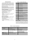
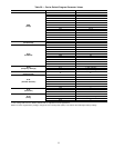
NOTE: The VFDs (part no. TOSVERT130-E3) are specially
modified for use on Carrier equipment. Some specifications
and control configuration defaults for Carrier applications
will differ from the VFD manufacturer manual included in
the packet. See Table 29 for listing of Carrier-specific de-
fault values.
STANDARDTRANSDUCER CONTROL— The VFDmoni-
tors and controls duct pressure (DP) via a differential pres-
sure transducer. The pressure transducer is located in the
auxiliary control box (034-048 units) or in the supply fan
compartment (see Fig. 34). The pressure transducer’s low
pressure reference port is connected to the outside of the unit
cabinet by a factory-installed tubing section. The pressure
transducer’s high pressure reference point must be field-
connected to the duct pressure pick-up (field-supplied and
installed in the supply duct).
The DP transducer monitors the static pressure in the sup-
ply duct and providesa4to20mAsignal directly to the
VFD. (Refer to Table 13 for transducer output signal (mA)
for actual duct static pressure.) The internal logic of the VFD
compares this signal representing actual duct pressure to the
user-configured DP set point. The VFD automatically ad-
justs its output to the supply fan motor to maintain the de-
sired DP set point. When operating with the factory-standard
DP transducer, the internal PID logic of the VFD is enabled.
EXTERNAL SIGNAL CONTROL — If the VFD is to be
controlled by an external control system other than the fac-
tory supplied pressure transducer, the internal PID logic func-
tion of the VFD must be disabled. To disable the PID
control:
1. Disconnect all power to the unit and the VFD.
2. Install a jumper across S2-CC (see Fig. 53 and 54 for
VFD terminal board connections).
3. Remove factory-supplied cable attached to IV and CC.
4. Remove other end of the same cable from the pressure
sensor.
5. Connect field supplied speed reference (4 to 20mA) across
terminals IV-CC.
6. Disable the supply fan motor operation.
7. Reconnect power to the unit and VFD.
8. Reprogram the VFD to accept an external reference (in
the Utility parameters group [Gr.Ut], set parameter item
Fnod [no.312] = 4).
9. Enable supply fan motor and return power to the unit.
SUPPLY FAN MOTOR OVERLOAD PROTECTION — The
VFD provides operating overload protection for the supply
fan motor. The factory has programmed the VFD overload
function to match the factory-installed motor (motor size and
efficiency). If the supply fan motor is changed from the origi-
nal factory selection, theoverload value may need to be changed
by the service person. Contact your local Carrier represen-
tative for assistance in determining the proper overload
setting.
NOTE: Variable frequency drive size is matched to factory-
installed motor size. Do not increase motor size without also
changing to equivalent VFD size.
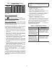
BLU
RED
YEL
AUX. SWITCH
LIMIT SWITCHES
CAPACITOR
CW
WINDING
(OPEN)
CCW
WINDING
(CLOSE)
CW
FEEDBACK
POTENTIOMETER
ECONOMIZER
MOTOR
BRAKE
WINDING
1
3
2
T1
T2
1
1
2
3
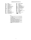
LEGEND
CCW — Counterclockwise
CW — Clockwise
Fig. 52 — Damper Motor Connection Diagram (VAV)
52