


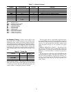
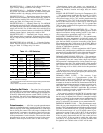

Table 7 — Switch Functions
SWITCH
NUMBER
CONFIGURATION VOLTAGE FUNCTION
SW-1 N.C. 115 Deenergize 115-v (OFC, Comp, IFC, Electric Heaters)
SW-2 N.C. 115 Deenergize TRAN7 (Process Board)
SW-3 N.O. 24 Energize EOR (Open Economizer Outside Air Dampers)
SW-4 N.O. 115 Energize IFC and CR-3 (IGV/VFD)
SW-5 N.C. 115 Isolate IFC and PEC for Separate Operation
SW-6 N.O. 115 Energize PEC (Power Exhaust)
SW-7 N.O. 24 Open PED at DPS
SW-8 N.C. 24 Block Auto-Close at DPS (Due to Low BP)
SW-9A/B
A: N.O.
B: N.C.
115 max Signal Room Terminals to Open (HIR1)
LEGEND
BP — Building Pressure
DPS — Differential Pressure Switch
EOR — Economizer Open Relay
HIR — Heat Interlock Relay
IFC — Indoor Fan Contactor
IGV — Inlet Guide Vane
N.C. — Normally Closed
N.O. — Normally Open
PEC — Power Exhaust Contactor
PED — Power Exhaust Damper
OFC — Outdoor Fan Contactor
VFD — Variable Frequency Drive
Air Pressure Tubing — Before options such as inlet
guide vanes (IGV), variable frequency drive (VFD), and/or
modulating power exhaust can operate properly, the pneu-
matic tubing for pressure sensing must be installed. Use fire-
retardent plenum tubing (field-supplied).Tubing size depends
on type of control device (see Table 8 below). Tubing must
be run from the appropriate sensing location (in the duct or
in the building space) to the control device location in the
unit.
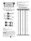
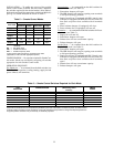
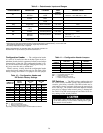
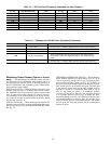
Table8—Tubing Size
OPTION UNITS
NOMINAL TUBE
SIZE (in.)
Inlet Guide Vanes (IGV) ALL
3
⁄
8
Variable Frequency
Drive (VFD)
ALL
1
⁄
4
Modulating Power Exhaust FK,FKX,JK,JKX
3
⁄
8
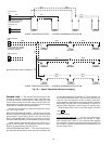
INLET GUIDE VANES — The tubing for the duct pressure
(DP) control option should sample supply duct pressure about
2
⁄
3
of the way out from the unit in the main trunk duct, at a
location where a constant duct pressure is desired.
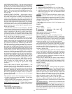
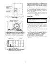
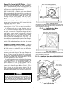
The inlet guide vanes are controlled by a differential pres-
sure switch (DPS). On sizes 034-048, the DPS is located in
the auxiliary control box at the economizer end of the unit
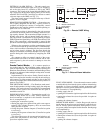
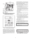
(see Fig. 33). On sizes 054-104, the DPS is located in the
supply fan section. See Fig. 34. Use a nominal
3
⁄
8
-in. plastic
tubing.
VARIABLE FREQUENCY DRIVE — The tubing for the
duct pressure (DP) control option should sample supply duct
pressure about
2
⁄
3
of the way out from the unit in the main
trunk duct, at a location where a constant duct pressure is
desired.
The duct pressure is sensed by a pressure transducer. The
pressure transducer output is directed to the VFD. On 034-
048 units the DP transducer is located in the auxiliary con-
trol box. On 054-104 units, the DP transducer is located in
the supply fan section. See Fig. 34. Use a nominal
1
⁄
4
-in.
plastic tubing.
23