


For units running Version 1.0 of the unit control software,
network access software is required to enable occupied heat-
ing. For units running Version 2.0 of the unit control soft-
ware, occupied heating is enabled or disabled by the posi-
tion of DIP switch no. 5.
Additional features may be provided with electronic ac-
cess to Unit Control Board. These features are:
• control board diagnostics
• compressor time guard override (power up, minimum off
and on times)
• compressor lockout during low supply-air temperature
• electronic expansion board features (if installed)
• field test capability
• control of the economizer damper and indoor fan to op-
tion unoccupied free cooling
• 365 day timeclock with backup (supports minute, hour, day,
month, and year)
• holiday table containing up to 18 holiday schedules
• occupancy control with 8 periods for unit operation
• support a set of display, maintenance, configuration, serv-
ice, and set point data tables for interface with Building
Supervisor, Comfort Works, or Service Tool
When a VAV unit with a space temperature sensor is ac-
cessed via a computer, the following additional features are
available:
• ability to initiate timed override from T-55 sensors
• ability to use multiple space temperature sensors to aver-
age space temperature
• temperature compensated start to calculate early start time
before occupancy
• provide space temperature reset to reset the supply air set
point upward when the temperature falls below the occu-
pied cooling set point
An electronic expansion board may be field-installed to
provide the following features:
• fan status
• filter status
• field-applied status
• demand limiting
• IAQ sensor
• OAQ sensor
• alarm light
When the unit is connected to the CCN (Carrier Comfort
Network), the following expansion board features can be
utilized:
• CCN IAQ (indoor air quality) participation
• CCN OAQ (outdoor air quality) participation
• CCN demand limit participation
• fire unit shutdown
• fire pressurization
• fire evacuation
• fire smoke purge
• modulated power exhaust override
A field-supplied space temperature sensor can be added to
provide the following:
• T-57 sensor will monitor room temperature
• T-55 sensor will monitor room temperature and provide
unoccupied override capability (1 hour)
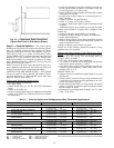
When the unit is equipped with a field-supplied space tem-
perature sensor and a remote contact closure (remote start/
stop), the occupied default set points will monitor unit op-
eration. The occupied default set points are 55 F (supply air)
cooling and 68 F (space temperature) heating (if electric heat
is installed). See Fig. 11 for remote start/stop wiring.
NOTE: For units without a space temperature sensor and which
have not had the base unit control board accessed via soft-
ware to set an occupancy schedule, the remote start/stop clo-
sure will allow the unit to operate in the pre-configured oc-
cupied default set points of 55 F (supply-air temperature)
cooling and 68 F (return-air temperature) heating. Without
an occupancy schedule, the unit will control to the unoccu-
pied default set points of 90 F (return air) cooling and 55 F
(return air) heating (if electric heat is installed).
Features with Network Applications — The base control board
provides, as standard, a connection for use with a Carrier
Comfort System and can also be integrated into a Carrier
Comfort Network. When the unit is accessed via a PC equipped
with Comfort Works, Building Supervisor, or Service Tool
software, the following features can be accessed:
• on-board timeclock can be programmed
• occupancy schedules can be programmed
• unit set points can be changed
• alarms can be monitored
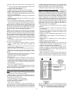
This access is available on the base control board via a
RJ-11 phone jack or a 3-wire connection to the communi-
cation bus. See Fig. 12. The timeclock has a 10-hour mini-
mum back-up time to provide for unit power off for servic-
ing unit or during unexpected power outages. For complete
Carrier Comfort System (CCS) or Carrier Comfort Network
(CCN) features and benefits, refer to the product literature.
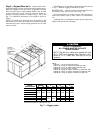
Step 7 — Make Electrical Connections
POWER WIRING — Units are factory wired for the voltage
shown on the unit nameplate. The main terminal block is
suitable for use with aluminum or copper wires and is sized
for single-point electric heat.
When installing units, provide a disconnect per NEC (Na-
tional Electrical Code) of adequate size (MOCP [maximum
overcurrent protection] of unit is on the informative plate).
All field wiring must comply with NEC and all local codes.
Size wire based on MCA (minimum circuit amps) on the
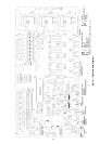
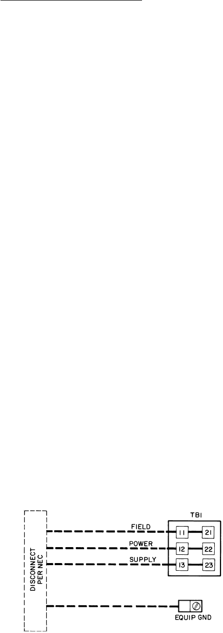
unit informative plate. See Fig. 13 for power wiring con-
nections to the unit power terminal block and equipment ground.
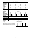
The main power terminal block is suitable for use with
aluminum or copper wire. See Fig. 13. Units have circuit
breakers for compressors, fan motors, and control circuit. If
required by local codes, provide an additional disconnect,
per NEC and local codes requirements, of adequate size
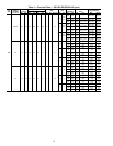
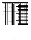
(Table 4). Whenever external electrical sources are used, unit
must be electrically grounded in accordance with local codes,
or in absence of local codes, with NEC, ANSI (American
National Standards Institute) C1-latest year.
All field wiring must comply with NEC and local code
requirements.
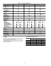
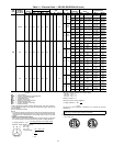
FIELD POWER SUPPLY — Unit is factory wired for volt-
age shown on nameplate. See Table 4 for electrical data.
Field wiring can be brought into the unit from bottom
(through basepan and roof curb) or through side of unit (cor-
ner post next to control box).
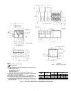
LEGEND
EQUIP — Equipment
GND — Ground
NEC — National Electrical Code
TB — Terminal Block
NOTE: Maximum wire size for TB1 is 500 MCM.
Fig. 13 — Field Power Wiring Connections
15