


Step 6 — Controls Options — The control options
that the units can provide are based on the following param-
eters: CV (constant volume) or VAV (variable air volume)
operation; stand-alone unit with field-supplied sensors in-
stalled (CV or VAV); as a system via the Carrier Comfort
System (TEMP or VVT); optional electronic expansion board
installed (CV or VAV); linked to the Carrier Comfort Net-
work; and availability of a computer and software (Comfort
Works, Building Supervisor, and Service Tool) to access the
base control board. See Table 3.
NOTE: Access to the base control board allows unit occu-
pancy schedules, unit timeclock, and various set points to be
changed from their factory-defined default settings.
CONSTANT VOLUME APPLICATIONS — The standard
CV unit is capable of being operated with either a Carrier-
approved thermostat or a field-supplied sensor. (See Price
Pages for ordering information.)
Features with Thermostat Control of Unit
• two-stage heating (if installed)
• two-stage cooling
• control of unit using Y1, Y2, W1, W2, and G thermostat
inputs
• control of the indoor fan
• outdoor air temperature/supply air temperature monitoring
• control of an outdoor air condenser fan based on outdoor
air temperature
• control of modulating economizer damper to provide free
cooling when outdoor conditions are suitable, using sup-
ply air temperature as a control point
• control of the economizer damper and indoor fan to obtain
unoccupied free cooling
• provide power exhaust output to an external power ex-
haust controller
• support a field test for field checkout
• control of 2 stages of CV power exhaust
• compressor Time Guard (power up and minimum off and
on times)
Additional features are provided by accessing the stand-
ard unit control board via software with a computer. These
features are:
• electronic expansion board features (if installed)
• compressor lockout during low supply air temperature
• control board diagnostics
• ability to change supply air set point (economizer control)
• ability to change high outdoor air temperature lockout set
point (economizer control)
• ability to change power exhaust set points
NOTE: A CV unit without a thermostat requires a field-
supplied sensor for operation.
Features with Sensor Control of Unit (Stand-Alone Appli-
cations — Unit control is limited to CV unoccupied default
set points, 90 F for cooling, 55 F for heating. There are
3 sensor options available:
• T-57 sensor will monitor room temperature
• T-55 sensor will monitor room temperature and provide
unoccupied override capability (1 hour)
• T-56 sensor will monitor room temperature, provide un-
occupied override capability (1 hour), and provide a tem-
perature offset of 5° F.
Standard features are:
• support of remote occupied/unoccupied input to start and
stop the unit
• cooling capacity control of 3 stages using economizer and
2 compressors to maintain space temperature to an occu-
pied or unoccupied set point
• enable heating (if installed) or cooling during unoccupied
periods as required to maintain space temperature within
the unoccupied set points
• adjustment of space temperature set points of ± 5° F when
using a T-56 sensor
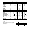
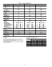
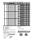
Table 3 — Controls Options and Configurations (Non-Thermostat Applications)
UNIT CONFIGURATION DEFAULT COOLING DEFAULT HEATING
UNITS RUNNING VERSION 1.0 UNIT CONTROL SOFTWARE
CV or VAV Unit with SPT Sensor
Unoccupied Cooling — 90 F (SPT)
Occupied Cooling — NA
Unoccupied Heating — 55 F (SPT)
Occupied Heating — NA
CV Unit with SPT Sensor and Remote
Start/Stop Switch
Unoccupied Cooling — 90 F (SPT)
Occupied Cooling — 78 F (SPT)
Unoccupied Heating — 55 F (SPT)
Occupied Heating — 68 F (SPT)
VAV Unit Remote Start/Switch Only
Unoccupied Cooling — NA
Occupied Cooling — 55 F (SAT)
Unoccupied Heating — NA
Occupied Heating — NA
VAV Unit with SPT Sensor and Remote
Start/Stop Switch
Unoccupied Cooling — 90 F (SPT)
Occupied Cooling — 55 F (SAT)
Unoccupied Heating — 55 F (SPT)
Occupied Heating — NA
UNITS RUNNING VERSION 2.0 UNIT CONTROL SOFTWARE
CV or VAV Unit with SPT Sensor
Unoccupied Cooling — 90 F (SPT)
Occupied Cooling — NA
Unoccupied Heating — 55 F (SPT)
Occupied Heating — NA
CV Unit with SPT Sensor and Remote
Start/Stop Switch
Unoccupied Cooling — 90 F (SPT)
Occupied Cooling — 78 F (SPT)
Unoccupied Heating — 55 F (SPT)
Occupied Heating — 68 F (SPT)
VAV Unit Remote Start/Stop Switch Only
Unoccupied Cooling — 90 F (RAT)
Occupied Cooling — 55 F (SAT)
Unoccupied Heating — 55 F (RAT)
Occupied Heating — 68 F (RAT)*
VAV Unit with SPT Sensor and Remote
Start/Stop Switch
Unoccupied Cooling — 90 F (SPT)
Occupied Cooling — 55 F (SAT)
Unoccupied Heating — 55 F (SPT)
Occupied Heating — 68 F (RAT)*
LEGEND
CV — Constant Volume SAT — Supply-Air Temperature
NA — Not Available SPT — Space Temperature
RAT — Return-Air Temperature VAV — Variable Air Volume
*With DIP Switch No. 5 configured to OPEN (Occupied Heat Enabled).
NOTE: Space temperature sensor and remote stop/switch are field-supplied.
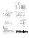
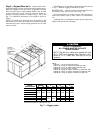
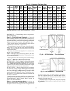
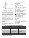
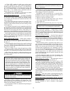
Fig. 10 — Condensate Drain Connections
(Typical Roof Curb or Slab Mount Shown)
12