


60
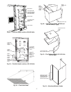
SPACE TEMPERATURE SENSOR (T-56) — The space tem-
perature sensor (P/N 33ZCT56SPT) wires are connected to
terminals in the unit main control box.
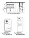
To connect the space temperature sensor, see Fig. 68.
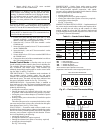
COMMUNICATING SPACE TEMPERATURE SENSOR
(T-58) — The communicating space temperature sensor (P/N
33ZCT58SPT) is wired to the Carrier Comfort Network
®
(CCN) connections on TB202.
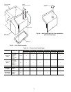
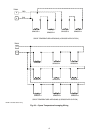
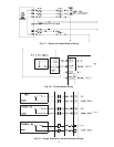
SPACE TEMPERATURE AVERAGING — Applications that
require averaging using multiple space temperature sensors can
be satisfied using either 4 or 9 sensors as shown in Fig. 69.
NOTE: Only Carrier sensors may be used for standard T-55
space averaging. Sensors must be used in multiples of 1, 4, and
9 only, with total sensors wiring not to exceed 1000 ft. How-
ever, space temperature reset can be accomplished with only
one sensor.
NOTE: Do not use T-56 sensors for space temperature averag-
ing because the 5-degree offset function will not work in a
multiple sensor application.
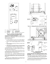
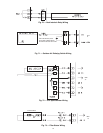
HEAT INTERLOCK RELAY (VAV Units Only — Not Neces-
sary For Digital Air Volume Applications) — Variable air vol-
ume (VAV) units using optimal start (morning warm-up) and/
or occupied heating require that room terminals be controlled
to the fully open position when the unit goes into Heating
mode. The HIR (heat interlock relay) function is provided for
this control. When the unit goes into Heating mode, the HIR is
energized to provide switch closure or opening (depending on
how the field-supplied power source is set up) to open the room
terminals. The field connections for the HIR are at TB201 ter-
minals 7 and 8. See Fig. 70.
Option and Accessory Control Wiring — The Z
Series units may be used in applications with additional control
features, options, or accessories. Refer to the Controls and
Troubleshooting manual for more information concerning
installation and configuration of options and accessories.
Figures 70-80 contain wiring information on the following
features:
• heat interlock relay (Fig. 70)
• outdoor air enthalpy switch (Fig. 71)
•CO
2
space sensor (Fig. 72)
• filter status switch (Fig. 73)
• fan status switch (Fig. 74)
• space humidity sensor (Fig. 75)
• return air humidity sensor (Fig. 75)
• return air CO
2
sensor (Fig. 76)
• return air smoke detector (Fig. 77)
• smoke control — fire shutdown (Fig. 78)
• smoke control — purge (Fig. 79)
• smoke control — evacuation (Fig. 79)
• smoke control — pressurization (Fig. 79)
• CCN connections (Fig. 80)
Carrier Comfort Network (CCN) Interface — The
48ZN,ZW,Z8 units can be connected to the CCN system if de-
sired. The communication bus wiring is supplied and installed
in the field. It consists of shielded, 3-conductor cable with shield
wire.
The system elements are connected to the communication
bus in a daisy chain arrangement. The positive pin of each
system element communication connector must be wired to the
positive pins of the system element on either side of it, the
negative pins must be wired to the negative pins, and the signal
pins must be wired to signal ground pins. Wiring connections
for the CCN system should be made at the terminal block using
the screw terminals. The board also contains an RJ14 CCN
plug that can be used to connect a Navigator™ device or field
service computer. There is also another RJ14 LEN (Local
Equipment Network) connection that is used to download soft-
ware. Consult CCN Contractor’s Manual for further
information.
NOTE: Conductors and drain wire must be 20 AWG minimum
stranded, tinned copper. Individual conductors must be insu-
lated with PVC, PVC/nylon, vinyl, Teflon, or polyethylene. An
aluminum/polyester 100% foil shield and an outer jacket of
PVC, PVC/nylon, chrome vinyl, or Teflon with a minimum
operating temperature range of –4 to 140 F (–20 C to 60 C) is
required. See Table 20 for cables that meet the requirements.
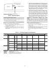
Table 20 — CCN Connection Approved
Shielded Cables
The following color code is recommended:
NOTE: If a cable with a different color scheme is selected, a
similar color code should be adopted for the entire network.
At each system element, the shields of its communication
bus cables must be tied together. If the communication bus is
entirely within one building, the resulting continuous field
must be connected to a ground at one point only. If the commu-
nication bus cable exits from one building and enters another,
the shields must be connected to grounds at the lightning
suppressor in each building where the cable enters or exits the
building (one point per building only).
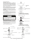
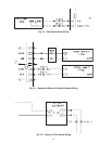
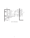
To connect the unit to the network (Fig. 80):
1. Turn off power to the control box.
2. Cut the CCN wire and strip the ends of the red (+), white
(ground) and black (–) conductors. (If a different network
color scheme is used, substitute appropriate colors.)
3. Wire the CCN to the screw terminals on the COMM
board as follows (Fig. 80):
a. Secure the red (+) wire to CCN screw terminal +
on the COMM board.
b. Secure the white (ground) wire to CCN screw
terminal C on the COMM board.
c. Secure the black (–) wire to CCN screw terminal –
on the COMM board.
CAUTION
Jumper MUST be in place between pins 1 and 3, 3 and 4
or inaccurate readings could result.
MANUFACTURER CABLE PART NO.
Alpha 2413 or 5463
American A22503
Belden 8772
Columbia 02525
IMPORTANT: When connecting the CCN communica-
tion bus to a system element, use a color coding system for
the entire network to simplify installation and checkout.
SIGNAL
TYPE
CCN BUS CONDUCTOR
INSULATION COLOR
COMM1 PLUG
PIN NO.
+ RED 1
GROUND WHITE 2
– BLACK 3