


55
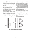
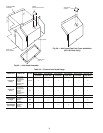
Compressor Mounting
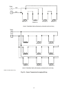
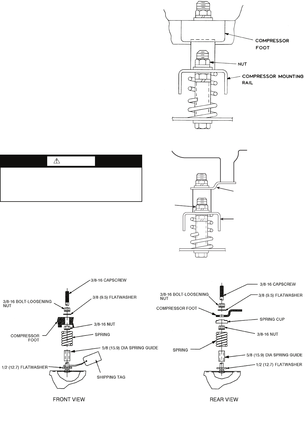
SIZES 030-090 — Each compressor is supported on
4 springs. The springs are compressed for shipment. After the
unit is installed, the holddown nuts need to be loosened for nor-
mal operation. See Fig. 55 for compressor mounting details.
Loosen each bolt using nut indicated until the flatwasher
(
3
/
8
-in.) can be moved with finger pressure. Do not remove the
locknuts. Check each compressor mounting to ensure all 4
springs have been loosened properly.
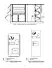
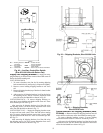
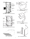
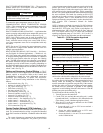
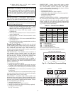
SIZE 105 — Compressors are mounted on rails and held
down by rail bolts during shipment. After unit is installed, loos-
en the rail bolts to allow the rails and compressors to float free-
ly on the springs located under the rails. See Fig. 56 and 57.
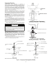
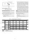
Gas Piping — Unit is equipped for use with natural gas
only. Installation must conform with local building codes, or in
the absence of local codes, with the National Fuel Gas Code
(NFGC), ANSI Z223.1.
A
1
/
8
-in. NPT tapping plug, accessible for test gage connec-
tion, must be field installed immediately upstream of gas sup-
ply connection to unit, but after manual gas valve. See Fig. 58.
Natural gas pressure at unit gas connection must not be less
than 5 in. wg or greater than 13 in. wg.
Size gas supply piping for 0.5 in. wg maximum pressure
drop. Do not use supply pipe smaller than unit gas connection.
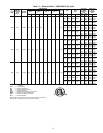
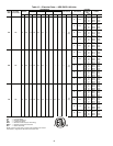
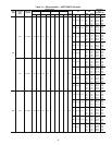
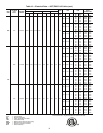
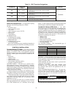
Optional Staged Gas Control — The 48Z030-105
large rooftop units may be ordered with an optional factory-
installed staged gas control system that monitors heating opera-
tion of the rooftop. The control system is composed of several
components as listed in sections below. Table 17 shows 48Z
Series staged gas implementation.
Refer to the Unit Controls and Troubleshooting book for in-
formation on configuring staged gas control.
CAUTION
Disconnect gas piping from unit when leak testing at pres-
sures greater than 0.5 psig. Pressures greater than 0.5 psig
will cause gas valve damage resulting in a hazardous con-
dition. If gas valve is subjected to pressure greater than
0.5 psig, it must be replaced.
Fig. 56 — Front View of Compressor
Mounting Rail Assembly — Size 105 Units
Fig. 57 — Rear View of Compressor
Mounting Rail Assembly — Size 105 Units
NUT
COMPRESSOR MOUNTING FOOT
COMPRESSOR MOUNTING RAIL
NOTE: All dimensions are in inches (mm).
Fig. 55 — Compressor Mounting (Sizes 030-090)