


56
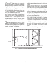
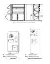
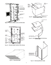
Installing Flue/Inlet Hoods — The flue and inlet
hoods are shipped in a package taped to the basepan in the fan
section. The flue (outlet) hoods are pre-assembled. The flue de-
flector and inlet hoods require assembly.
The hoods are located on the heating section access panel as
shown in Fig. 59 (sizes 030-050) or Fig. 60 (sizes 055-105).
See Table 18 for a list of parts used to assemble each hood and
quantities of each hood type used with each unit.
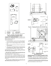
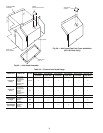
1. Remove shipping block-offs and shipping tape from all
openings in the access panel.
2. Attach flue outlet hoods (see Fig. 61) to access panel us-
ing screws provided. Hoods are placed over each com-
bustion outlet.
3. Install flue deflector baffle inside flue deflector hood. See
Fig 62 for sizes 030-050 and 075-105 (V-type deflector).
See Fig. 63 for sizes 055-105 (curve-type deflector). In-
stall flue deflector hood assembly over each flue outlet
hood (installed in Step 2). Observe the offset mounting
hole locations in the deflector hood flanges when attach-
ing hood to panel (see Fig. 64). Holes in the mounting
flange must be at the bottom when attached.
4. Inlet hoods are shipped unassembled and must be assem-
bled on the access panel (see Fig. 65). Flanges of the
hood top and sides should be placed on the inside of the
access panel openings. Install hood top and sides with
screws provided. Attach speed clips to screen and insert
screen into bottom opening of hood. Secure with 3
screws. On large inlet hoods, attach viewport cover over
opening in hood (see Fig. 66). Secure with two screws.
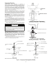
Supply-Air Thermistors (Staged Gas Units
Only) — Supply-air thermistors are a field-installed, factory-
provided component. Three supply-air thermistors are shipped
with staged gas units inside the heating section. Thermistor
wires must be connected to SGC in the heating section. See
Table 19. The supply-air thermistors should be located in the
supply duct with the following criteria:
• downstream of the heat exchanger cells
• equally spaced as far as possible from the heat
exchanger cells
• a duct location where none of the supply air thermistors
are within sight of the heat exchanger cells
• a duct location with good mixed supply air portion of the
unit.
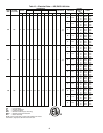
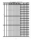
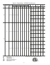
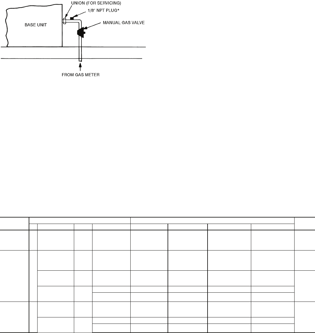
Table 17 — 48Z Series Staged Gas Implementation
LEGEND
*NPT plug is field supplied.
NOTE: Follow all local codes.
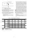
Fig. 58 — Gas Piping Details
NO. OF
STAGES
MODEL NUMBER POSITION POINT
HEAT
SIZE
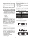
3 5 6,7,8 10 HTSTGTYP CAPMXSTG LIMTHIHT LIMTLOHT
2 stages Z H, K, W, Y 030
035
040
050
ALL Default=0 Default=45 Default=170 F Default=160 F Low
5 stages Z J, L, X, Z 030
035
040
050
ALL Default=1 Default=20 Default=170 F Default=160 F High
H, K, W, Y 055
060
070
ALL Default=1 Default=20 Default=135 F Default=125 F Low
H, K 075
090
105
-,A,B,C,D,E Default=1 Default=20 Default=135 F Default=125 F
G,H,J,K,L,M Default=1 Default=20 Default=130 F Default=120 F
9 stages Z J, L, X, Z 055
060
070
ALL Default=3 Default=15 Default=135 F Default=125 F High
J, L 075
090
105
-,A,B,C,D,E Default=3 Default=15 Default=135 F Default=125 F
G,H,J,K,L,M Default=3 Default=15 Default=130 F Default=120 F
CAPMXSTG — Maximum Capacity per Changes
HTSTGTYP — Heat Stage Type
LIMTHIHT — Limit Switch Thermistor High Temperature
LIMTLOHT — Limit Switch Thermistor Low Temperature