


33
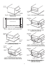
Install Outdoor Hoods (48ZG,ZN,Z6,Z8 Units)
UNIT SIZES 030-050
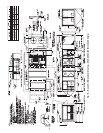
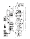
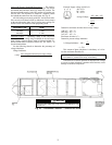
25% Outdoor-Air Hoods (Units without Economizer
Option) (Fig. 29)
1. Outdoor-air hoods are shipped bolted to the unit in a ship-
ping position. Remove the 6 screws holding each 25%
outdoor air hood shipping cover in place.
2. Remove the holddown screw from each upper corner of
each hood.
3. Pivot hoods outward (2 hoods).
4. Install 17 screws around outside of each hood. (Screws
are in the fastener package taped to the basepan inside the
fan section.)
5. Apply a bead of RTV or similar sealant to corner of each
hood at pivot point to prevent water leaks. See Fig. 30.
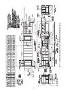
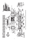
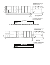
Economizer Hoods (Units with Economizer Option)
(Fig. 31 and 32)
1. Remove the 4 screws holding each of the 2 economizer
side hoods in place.
2. Pivot hoods outwards (2 hoods).
3. Apply seal strip to vertical flange of hood sides.
4. Install hood sides of hood top using 19 screws (7 each
side, 5 top). Screws are in fastener package located with
the hood sides and seal strip which is taped inside the
unit.
5. Apply a bead of RTV or similar sealant to corners of
economizer hoods to prevent water leaks.
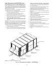
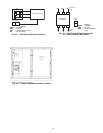
UNIT SIZES 055-105
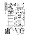
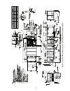
25% Outdoor-Air Hoods (Fig. 33)
— The outdoor-air hoods
are factory installed on the 055-105 units.
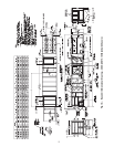
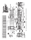
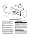
Economizer Hoods (Units with Economizer Option) (Fig. 34-36)
1. Remove the 6 screws holding each of the 4 economizer
shipping covers in place.
2. Remove the holddown screw from each upper corner of
each economizer hood.
3. Pivot hoods outward (4 hoods).
4. Apply seal strip to vertical flange of hood sides.
5. Install 18 screws (5 each side, 6 top, and 2 bottom)
around the outside of each hood. (Screws are in the fas-
tener package taped to the basepan inside the fan section.)
6. Apply a bead of RTV or similar sealant to corner of econ-
omizer hood at pivot point to prevent water leaks. (See
Fig. 30.)
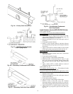
Fig. 24 — Primary Drain Connection
A = 4-in. (102 mm) min — Sizes 030-070
7-in. (178 mm) min — Sizes 075-105
Fig. 25 — Slab-Mounted Condensate
Drain Piping Details
Fig. 26 — Secondary Condensate Drain Location
Fig. 27 — Secondary Drain Seal Plate Location
A = 4-in. (102 mm) min — sizes 030-070
7-in. (178 mm) min — sizes 075-105
Fig. 28 — Curb-Mounted Condensate
Drain Pipe Details