


5
Heat Exchanger —
To ensure dependable and efficient
heating operation, the heat exchanger should be checked by a
qualified maintenance person before each heating season, and
cleaned when necessary. This checkout should not be attempt-
ed by anyone not having the required expertise and equipment
to do the job properly. Checking and/or cleaning the heat
exchanger involves removing the gas controls assembly and
the flue collector box cover and, when completed, reinstalling
the gas controls assembly for proper operation. Also, the flue
collector box cover must be replaced correctly so that a proper
seal is maintained. Contact your dealer for the required period-
ic maintenance.
Fans and Belts —
Periodically check the condition of
fan wheels and housings, and belt tension. When service is nec-
essary, call your dealer.
Evaporator-, Condenser-, and Combustion
Fan Motors —
Lubrication is not recommended. Bearings
will not require lubrication for at least 5 years of normal opera-
tion. After 5 years, motor life can be extended by having the
motors serviced at an authorized motor service shop.
Fan Shaft Bearings —
Lubrication is not recommend-
ed. When service is necessary, call your dealer.
Evaporator and Condenser Coils —
Cleaning of the
coils should only be done by qualified service personnel. Con-
tact your dealer for the required annual maintenance.
Condensate Drain —
The drain pan and condensate
drain line should be checked and cleaned at the same time the
cooling coils are checked by your dealer.
Compressor —
All compressors are factory shipped with
a normal charge of the correct type refrigeration grade oil in
them and should rarely require additional oil. The service tech-
nician must be certain the proper oil level is maintained in the
compressor when it is installed and running.
Condenser Fan
The fan must be kept free of all obstructions to ensure
proper cooling. Contact your dealer for any required service.
Electrical Controls and Wiring —
Electrical controls
are difficult to check without proper instrumentation; therefore,
if there are any discrepancies in the operating cycle, contact
your dealer and request service.
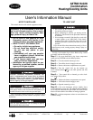
Integrated Gas Controller (IGC) —
The IGC board
incorporates an LED that emits a flashing light to indicate an
alarm code. If the furnace section will not operate and the LED
is flashing a code (2 to 8 flashes in succession), contact your
dealer and request service. See Fig. 1.
Refrigerant Circuit —
The refrigerant circuit is difficult
to check for leaks without the proper equipment; therefore, if
inadequate cooling is suspected, contact your dealer for service.
Combustion Area and Vent System —
The com-
bustion area and vent system should be visually inspected
before each heating season. The normal accumulation of dirt,
soot, rust, and scale can result in loss of efficiency and improp-
er performance if allowed to build up.
See Fig. 1 and proceed as follows to inspect the combustion
area and power-venting system of your unit.
1. Turn off electrical power and gas supply to your unit.
2. Remove burner compartment access panel.
Do not poke sticks, screwdrivers, or any other object into
revolving fan blades. Severe bodily injury may result.
If your unit makes an especially loud noise when the main
burners are ignited, shut down the heating section and call
your dealer.
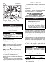
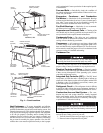
BURNER ACCESS
PANEL (HIDDEN)
HOOD
(OPTION)
OUTDOOR-AIR
FILTER
RETAINER
OUTDOOR-AIR
FILTERS
MOTORS AND FILTER
ACCESS PANEL
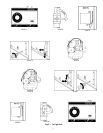
MOTOR AND
FILTER
ACCESS PANEL
HOOD
(OPTION)
BURNER ACCESS
PANEL (HIDDEN)
OUTDOOR-
AIR FILTERS
OUTDOOR-
AIR FILTER
RETAINER
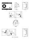
OUTDOOR-
AIR FILTER
RETAINER
OUTDOOR-
AIR FILTERS
MOTOR AND FILTER
ACCESS PANEL
HOOD
(OPTION)
BURNER ACCESS
PANEL (HIDDEN)
48TM016, 020
48TM025
48TM028
Fig. 4 — Panel Locations