


2
TO SHUT UNIT OFF
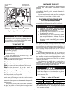
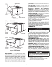
See Fig. 1 for location of gas valve. Refer to Fig. 3 while
proceeding with the following steps.
Step 1 —
Set room thermostat to lowest temperature setting
and set SYSTEM switch to OFF position.
Step 2 —
Close the external manual gas valve.
Step 3 —
Turn off the electrical power supply to the unit.
Step 4 —
Remove the burner compartment access panel.
Step 5 —
Turn the control dial on the internal gas
valve counterclockwise to the OFF position.
Step 6 —
Replace the burner compartment access panel.
Step 7 —
If unit is being shut down because of a malfunc-
tion, call your dealer as soon as possible.
If unit is being shut down because the heating season has
ended, restore electrical power to the unit to ensure operation
of the cooling system during the cooling season.
Should overheating occur, or the gas supply fail to shut off,
shut off the manual gas valve to the unit before shutting off the
electrical supply.
Do not use this unit if any part has been under water. Imme-
diately call a qualified service technician to inspect the unit and
to replace any part of the control system and any gas control
which has been under water.
MAINTAINING YOUR UNIT
All maintenance should be handled by skilled, experienced
personnel. Your dealer can help you establish a standard
procedure.
For your safety, keep the area around the unit clear and free
of combustible materials, gasoline, and other flammable liq-
uids and vapors.
To assure proper functioning of the unit, flow of combustion
and ventilating air must not be obstructed from reaching the
unit. Clearance of at least 4 ft on all sides is required.
ROUTINE MAINTENANCE AND CARE
FOR THE EQUIPMENT OWNER
Before proceeding with those things you might want to
maintain yourself, please carefully consider the following:
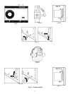
Air Filters —
Air filters should be checked at least every 3
or 4 weeks and changed or cleaned whenever they become
dirty. Table 1 indicates the correct filter size for your unit. Re-
move the filter access panel to replace or inspect the filters. All
units have filter tracks into which the filters slide. Remove the
filters by pulling outward from the track. See Fig. 4 for filter
access panel location. Note the direction of flow arrows on the
filter frame.
For horizontal supply/return units, the size, location and
number of air filters varies from Table 1. If you have difficulty
in locating your air filter in the return-air duct system, or if you
have questions concerning proper filter maintenance, contact
your dealer for instructions. When replacing your unit filters,
always use the same size and type of filter that was originally
supplied by the installer.
Units with outdoor air capability have a cleanable filter for
the outdoor air. This filter should be checked annually and
cleaned as necessary. Remove by removing screws in outdoor
air filter retainer and sliding filters out of the unit.
Table 1 — Indoor-Air Filter Data*
*When replacing filters, always use the same type and size origi-
nally supplied.
†The 48TM028 unit requires 2-in. industrial grade filters capable of
handling face velocities of up to 625 ft/min (such as American Air
Filter no. 5700 or equivalent).
If the pilot fails to light, the main burner fails to light, or the
blower fails to come on, shut down gas heating section and
call your dealer for service. Failure to follow these require-
ments could result in serious personal injury.
Do not turn off the electrical power to unit without first
turning off the gas supply.
Failure to follow these procedures can result in serious
fire or personal injury.
1. TURN OFF GAS SUPPLY AND ELECTRICAL
POWER TO YOUR UNIT BEFORE SERVICING
OR PERFORMING MAINTENANCE.
2. Do not turn off electrical power to this unit without
first turning off the gas supply.
3. When removing access doors or performing mainte-
nance functions inside your unit, be aware of sharp
sheet metal parts and screws. Although special care
has been taken to reduce sharp edges to a minimum,
be extremely careful when handling parts or reaching
into the unit.
Never operate your unit without filters in place. Failure to
heed this warning may result in damage to the blower
motor and/or compressor. An accumulation of dust and lint
on internal parts of your unit can cause loss of efficiency
and in some cases, fire.
UNIT SIZE
48TM
TYPE OF
FILTER
QUANTITY...SIZE (in.)
016-028†
Fiberglass
Throwaway
4...20 x 20 x 2
4...16 x 20 x 2
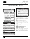
INTEGRATED GAS
UNIT CONTROLLER
(HIDDEN)
INDUCED DRAFT
MOTOR
FLUE BOX
COVER
MAIN BURNER
SECTION
MAIN GAS
VALVE
COMBUSTION
FAN HOUSING
Fig. 1 — Typical Gas Heating Section