


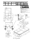
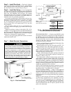
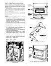
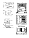

Step 5 — Install Flue Hood — Flue hood is shipped
screwed to the burner compartment access panel. Remove
from shipping location and, using screws provided, install
flue hood and screen in location shown in Fig. 8.
Step 6 — Install Gas Piping — Unit is equipped for
use with type of gas shown on nameplate. Refer to local build-
ing codes, or in the absence of local codes, to ANSI Z223.1-
latest year and addendum Z223.1A-latest year entitled
National Fuel Gas Code. In Canada, installation must be in
accordance with the CAN1.B149.1 and CAN1.B149.2 in-
stallation codes for gas burning appliances.
For natural gas applications, gas pressure at unit gas con-
nection must not be less than 4.0 in. wg (5.0 in. wg in high
heat units) or greater than 13.0 in. wg while unit is operat-
ing. For liquid propane applications, the gas pressure must
not be less than 5.0 in. wg or greater than 13.0 in. wg at the
unit connection.
Size gas supply piping for 0.5 in. wg maximum pres-
sure drop. Do not use supply pipe smaller than unit gas
connection.
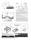
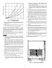
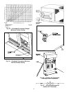
Support gas piping as shown in the table in Fig. 9. For
example, a
3
⁄
4
-in. gas pipe must have one field-fabricated sup-
port beam every 8 ft. Therefore, an 18-ft long gas pipe would
have a minimum of 2 support beams, and a 48-ft long pipe
would have a minimum of 6 support beams.
See Fig. 9 for typical pipe guide and locations of external
manual gas shutoff valve.
Step 7 — Make Electrical Connections
Unit cabinet must have an uninterrupted, unbroken elec-
trical ground to minimize the possibility of personal in-
jury if an electrical fault should occur. This ground may
consist of electrical wire connected to unit ground lug
in control compartment, or conduit approved for elec-
trical ground when installed in accordance with NEC
(National Electrical Code), ANSI/NFPA (National Fire
Protection Association), latest edition, and local elec-
trical codes. Do not use gas piping as an electrical ground.
Failure to follow this warning could result in the in-
staller being liable for personal injury of others.
FIELD POWER SUPPLY —All units except 208/230-v units
are factory wired for the voltage shown on the nameplate. If
the 208/230-v unit is to be connected to a 208-v power sup-
ply, the transformer must be rewired by moving the black
wire from the 230-v red wire on the transformer and con-
necting it to the 200-v blue wire from the transformer. The
red wire then must be insulated.
Refer to unit label diagram for additional information. Pig-
tails are provided for field service.
When installing units, provide a disconnect per NEC. Use
copper conductors only when splice connectors are used.
All field wiring must comply with NEC and local require-
ments. In Canada, electrical connections must be in accor-
dance with CSA (Canadian Standards Association) C22.1
Canadian Electrical Code Part One.
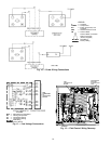
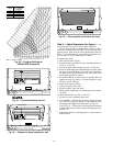
Install conduit through side panel openings indicated in
Fig. 7. Route power lines through connector to terminal con-
nections as shown in Fig. 10.
On 3-phase units, voltages between phases must be bal-
anced within 2% and the current within 10%. Use the for-
mula shown in Table 2, Note 2 to determine the percentage
of voltage imbalance. Operation on improper line voltage or
excessive phase imbalance constitutes abuse and may cause
damage to electrical components. Such operation would in-
validate any applicable Carrier warranty.
NOTE: If field-installed thru-the-bottom connections are used,
refer to the accessory installation instructions for power wir-
ing. Refer to Fig. 7 for drilling holes in basepan.
FIELD CONTROL WIRING — Install a Carrier-approved
accessory thermostat assembly according to installation in-
structions included with the accessory. Locate thermostat as-
sembly on a solid wall in the conditioned space to sense av-
erage temperature in accordance with thermostat installation
instructions.
NOTE: For wire runs up to 50 ft, use no. 18 AWG (Ameri-
can Wire Gage) insulated wire (35 C minimum). For 50 to
75 ft, use no. 16 AWG insulated wire (35 C minimum). For
over 75 ft, use no. 14 AWG insulated wire (35 C minimum).
All wire larger than no. 18 AWG cannot be directly con-
nected to the thermostat and will require a junction box and
splice at the thermostat.
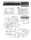
Fig. 8 — Flue Hood Details
LEGEND
NFGC — National Fuel Gas Code
*Field supplied.
NOTE: Follow all local codes.
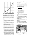
SPACING OF SUPPORTS
STEEL PIPE
NOMINAL
DIAMETER
(in.)
X
DIMENSION
(feet)
1
⁄
2
6
3
⁄
4
or 1 8
1
1
⁄
4
or larger 10
Fig. 9 — Gas Piping Guide (With Accessory
Thru-the-Curb Service Connections)
8