


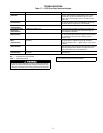
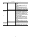


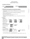

Table 19 — PARABLADE Economizer Service Troubleshooting
PROBLEM CAUSE REMEDY
Damper does not
open.
Evaporator fan not on. Check wiring between G on connection board and indoor (evaporator)
fan contactor.
No power to economizer motor. 1. Disconnect power at TR and TR1. Disconnect jumper across P
and P1.
2. Connect jumper across TR and 1.
3. Connect jumper across T1 and T.
4. If connected, remove enthalpy sensor from terminals S
o
and +.
Factory-installed 620 ohm resistor should be connected to termi-
nals S
R
and +.
5. Apply power (24 vac) to terminals TR and TR1. The LED should
be off and the damper should be in the closed position.
6. Disconnect the factory-installed 620 ohm resistor from terminals
S
R
and +. The LED should light up and the motor should drive to-
wards open. If this does not happen, replace the economizer con-
trol module.
Economizer motor failure. If the indoor (evaporator) fan and economizer motor are energized,
verify that there is a minimum of 24 vac at terminals TR and TR1. If
the motor is not operating, replace the motor.
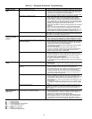
Economizer opera-
tion limited to mini-
mum position.
Economizer control module
failure.
1. To simulate high or low enthalpy, reconnect the factory-installed
620 ohm resistor across terminals S
R
and +.
2. Connect 1.2 Kohm checkout resistor across terminals S
o
and +.
Turn the enthalpy set point to ‘‘A.’’ The LED should turn on, indi-
cating low enthalpy. The motor should drive towards open. If LED
does not light, replace module. If motor does not drive open, check
motor operation.
3. Turn the enthalpy set point to ‘‘D.’’ The LED should turn off, indi-
cating high enthalpy. The motor should drive towards closed. If
these actions do not occur, replace module.
4. Disconnect 1.2 Kohm checkout resistor before resuming operation.
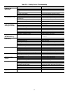
Damper does not
close.
No power to economizer. 1. Disconnect power at TR and TR1. Disconnect jumper across P
and P1.
2. Connect jumper across TR and 1.
3. Connect jumper across T1 and T.
4. If connected, remove enthalpy sensor from terminals S
o
and +.
Factory-installed 620 ohm resistor should be connected to termi-
nals S
R
and +.
5. Apply power (24 vac) to terminals TR and TR1. The LED should
be off and the damper should be in the closed position.
6. Disconnect the factory-installed 620 ohm resistor from terminals
S
R
and +. The LED should light up and the motor should drive to-
wards open. If this does not happen, replace the economizer con-
trol module.
Spring return failure. If power to unit is off and damper does not close, check for a bound
linkage. If linkage is not bound, then internal spring may be broken.
Replace actuator.
Economizer motor failure. If the economizer control module is functioning properly, verify that
there is a minimum of 24 vac at terminals TR and TR1. If the motor is
not operating, replace the motor.
Damper does not
open or
close according to
enthalpy
readings.
Sensor incorrectly wired or bad. To verify sensor operation, reconnect the + lead of the outdoor en-
thalpy sensor to the + terminal of the economizer control module.
Connect a DC milliammeter between terminals S
o
of the economizer
control module and terminal S of the enthalpy sensor. The milliamme-
ter should indicate between 3 and 25 mA if the sensor is operating
properly. If the milliammeter indicates 0, the sensor may be wired
backwards. If any other readings are shown, replace the sensor.
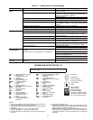
LEGEND
LED — Light-Emitting Diode
33