


25
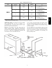
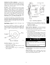
Individual Fan Wheel Adjustment -- Loosen the 2
locking bolts holding fan wheel hub to shaft. See Fig. 23.
Position fan wheel in center of the fan housing and tighten
locking bolts. Clearance between wheel and housing
should be the same on both sides.
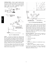
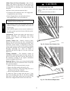
Fan Belts -- Motor mounting plate and motor support
angles are slotted to permit both vertical and horizontal
adjustment. Adjust belt(s) for correct deflection by
loosening motor plate mounting bolts, moving motor/plate
assembly forward or back, and re tightening bolts. Press
down on belt with one finger midway between fan and
motor pulleys to check deflection. For units with motor
sizes up to and including 3.7 Hp (2.76 kW), correct
deflection is
3
/
16
--in. (4.8 mm). For larger motor sizes,
correct deflection is
1
/
8
--in. (3.2 mm). See Fig. 25.
If complete belt replacement is required during servicing,
loosen the motor plate mounting bolts (Fig. 25), move
motor/plate assembly towards fan pulley, and pull belt(s)
off pulleys. Reverse the procedure with new bolts and
readjust deflection.
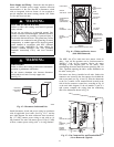
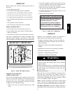
Fan Rotation -- Correct fan rotation with respect to fan
outlet is shown in Fig. 26.
To reverse the direction of rotation of a 3--phase fan
motor, reverse any 2 of the power leads. Refer to the
connection diagram on the inside of motor terminal box
cover for proper reversing procedure of single--phase
motor.
C10701
Fig. 26 -- Fan Rotation
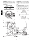
Fan Pulley Alignment -- Align as follows:
1. Loosen setscrews on pulleys.
2. Align pulleys visually and tighten setscrews on fan
pulley to lock it in place.
3. Use the methods shown in Fig. 27 to check proper
pulley alignment.
C10702
Fig. 27 -- Fan Pulley Adjustments
4. If pulleys are not in correct alignment, loosen the mo-
tor holddown bolts and slide the motor axially until
the pulleys are aligned.
5. Tighten motor holddown bolts.
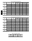
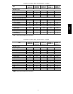
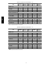
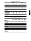
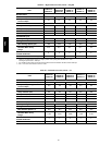
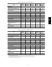
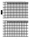
Pulley and Drive Adjustment -- To obtain desired fan
speed, refer to the fan motor and drive data in Tables
8A--11D and adjust fan motor pulley as follows:
1. Remove belt from fan motor pulley after loosening
motor from motor base.
2. Loosen setscrew in moveable flange of pulley. Screw
moveable flange toward fixed flange to increase the
fan speed and away from fixed flange to reduce
speed. Before tightening setscrew, make certain that
setscrew is over nearest flat surface of pulley hub
(Fig. 27).
UNIT OPERATION HAZARD
Failure to follow this caution could cause equipment
damage.
Increasing fan speed produces a greater load on motor.
Do not exceed rated capacity of motor.
CAUTION
!
Condensate Drains -- Keep condensate drains free of dirt
and foreign matter.
Return--Air Filters -- Refer to Replacing Filters section
for filter accessibility and removal. Replace with clean
filters of the sizes listed in Tables 1A--1F.
40RU