


23
START--UP
Before starting unit, check the following and correct as
necessary:
S Is unit solidly supported?
S Is fan adjusted for speed and pulley alignment?
S Are pulleys, motor, and bearings securely mounted?
S Are there any loose parts that will rattle or vibrate?
S Is condensate drain pan pitched for correct drainage?
S Are coil baffle plates tight against coil to prevent air
bypass?
S Are all panels securely fastened?
S Are all electrical connections correct and tight?
40RUA and 40RUQ ONLY —
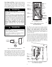
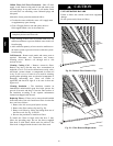
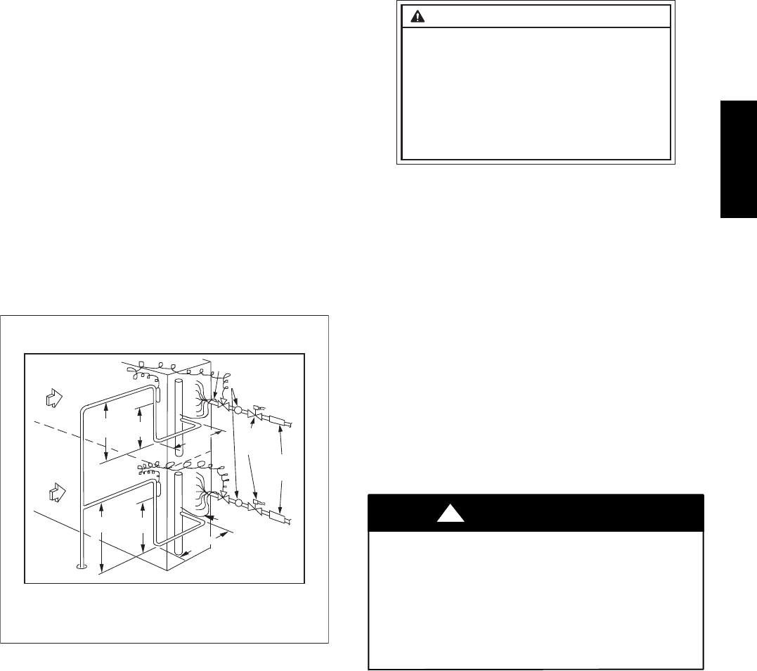
S Is TXV bulb located on suction tube per Fig. 21?
S Is the capillary tube to the bulb free of kinks and not
subject to pinching?
S Is the bulb well secured to the suction tube with strap?
Also refer to condensing unit or outdoor heat pump section
instructions before starting a split system. A split system
start--up checklist is provided at the end of these instructions.
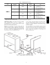
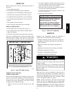
IMPORTANT! / IMPORTANT
40RU500072 2.0
The sensor bulb capillary tubes must be routed from the TXVs inside the unit through one of the piping
access holes. Clamp the TXV sensor bulb on a vertical portion of the suction line, outside the unit.
See Fig. 7 in the installation, start-up and service instruction. Super heat must be adjusted in field.
Les tubes capillaires du capteur doivent être acheminé à partir du détendeur thermostatique situé à l'intérieur
de l'appareil au travers de l'un des trous d'accès de conduites. Attacher le capteur sur une portion verticale
de la conduite de succion, à l'extérieur de l'appareil. Voir la Figure 7 dans le manuel d'installation, de mise
en marche, et d'entretien. La surchauffe doit être ajustée sur place.
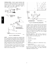
AIR FLOW
CIRCULATION
D'AIR
UPPER SPLIT
BLOC SUPÉRIEUR
LOWER
SPLIT
BLOC
INFÉRIEUR
AIR FLOW
CIRCULATION
D'AIR
15 DIAMS MIN
15 x DIA. MIN
10 DIAMS
10 x DIA. MIN
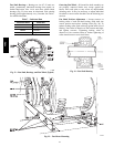
TXV SENSING
BULB
CAPTEUR TXV
15 DIAMS MIN
15 x DIA. MIN
10 DIAMS
10 x DIA. MIN
TXV
SENSING
BULB
CAPTEUR TXV
EQUALIZER LINE
CONDUITE D'ÉQUILIBRAGE
SIGHT GLASS
HUBLOT
8 DIAMS MIN
8 x DIA. MIN
TXV
SOLENOID
VALVE
VANNE
SOLÉNOÏDE
FILTER
DRIER
FILTRE
DESSICCATEUR
TXV
EQUALIZER LINE
CONDUITE D'ÉQUILIBRAGE
8 DIAMS MIN
8 x DIA. MIN
INDOOR COIL
ÉCHANGEUR INTÉRIEUR
C10827
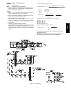
Fig. 21 -- Label, TXV Bulb Location
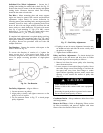
Adjusting TXV for Superheat
(40RUA and RUQ only) —
The unit--mounted thermostatic expansion valve(s) is/are
factory set to provided superheat at the bulb location in
10_Fto15_F (5.5_Cto8.3_C) range. Actual system load
conditions may require adjustment of the factory setting.
To adjust the TXV superheat setting:
1. Remove the seal cap from the bottom of the TXV
body.
2. To increase superheat, turn the stem clockwise. To de-
crease the superheat, turn the stem counterclockwise.
Do not turn the stem more than one full turn.
3. Wait until suction pressure and superheat stabilize.
This may take more than 30 minutes.
4. Continue adjustment until superheat reaches 10_Fto
15_F (5.5_Cto8.3_C).
5. Replace the seal cap; tighten.
INSTALLER / INSTALLATEUR
TXV superheat must be checked at initial
unit start-up and adjusted if necessary.
Superheat must be 10 - 15 deg F.
La surchauffe TXV doit être vérifiée au
moment de la mise en route initiale et
ajustée si nécessaire. La surchauffe doit
être comprise entre 10 et 15 degrés F.
40RU500073 2.0
C10828
Fig. 22 -- Label, TXV Adjustment
SERVICE
Inspection and maintenance should be performed at
regular intervals and should include the following:
S Complete cleaning of cabinet, fan wheel, cooling coil,
condensate pan and drain, heating coils, and return--air
grille (if present).
S Inspection of panels and sealing of unit against air
leakage.
S Adjustment of fan motor, belt, bearings, and wheels.
S Cleaning or replacement of filters.
S Testing for cooling/heating system leaks.
S Checking of all electrical connections.
ELECTRICAL SHOCK HAZARD
Failure to follow this warning could result in personal
injury or death.
Before performing service or maintenance operations
on unit, always turn off main power switch to unit and
install lockout tag. Unit may have more than one
power switch.
!
WARNING
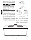
Most unit service can be performed by removing one or
both of the unit’s side panels. Coil cleaning or removal or
insulation cleaning may require removal of a rear, top, or
bottom panel, depending on the unit’s orientation. When
service is completed, replace unit panels.
Panels -- Panels are fastened to unit frame with sheet metal
screws. Fan and coil compartment must be sealed tightly
after service to prevent air from bypassing the cooling coil.
Fan Motor Lubrication -- Fan motor supplied with unit is
permanently lubricated and requires no further lubrication.
40RU