


6
Quiet Shift
Quiet shift is a field selectable defrost mode (factory set to OFF),
which will eliminate occasional noise th at could be heard a t the
start of defrost cycle and restartin g of heating c ycle. It is selected
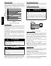
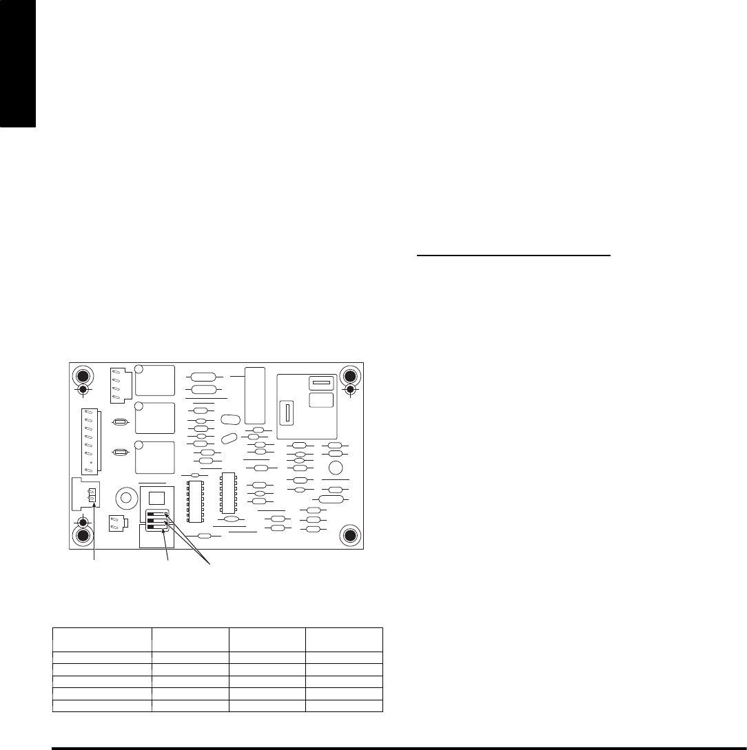
by placing DIP switch 3 on defrost board (see Fig. 9) in the ON
position.
When Quiet Shift switch i s placed in ON position, and a defrost is
initiated, the following sequence of operation will occur . Reversing
valve will energize, compressor will turn off for 30 seconds, and
then turn back on to complete defrost. At the start of heating after
conclusion of defrost, reversing valve will de--energize,
compressor will turn off for another 30 seconds, and the fan will
turn off for 40 seconds, before starting in the heating mode.
Defrost
The defrost control is a time/temperature control which has field
selectable settings of 30, 60, 90, or 120 minutes, factory set to 90
minutes. These settings represent the amount of time that must pass
after closure of the defrost thermostat before the defrost sequence
begins.
The defrost thermostat senses coil temperature throughout the
heating cy cle. W h en the coil tem p eratu re reaches the d efro st
therm o stat setting o f ap p roxim ately 32_F, it w ill close, wh ich
energizes the DFT terminal and begins the defrost timing sequence.
When the DFT has been energized for the selected time, the defrost
cycle begins. Defrost cycle is terminated when defrost thermostat
opens, or automatically after 10 minutes.
Defrost Speedup
To initiate a forced defrost, speedup pins (J1) must be shorted with
a flat head screwdriver for 5 seconds and RELEASED.Ifthe
defrost thermostat is open, a short defrost cycle will be observed
(actual length depends on Quiet Shift switch position). When Quiet
Shift is off, only a short 30 second defrost cycle is observed. With
Quiet Shift ON, the speedup sequence is one minute; 30 second
compressor off period followed by 30 seconds of defrost with
compressor operation. When returning to heating mode, the
compressor will turn off for an additional 30 seconds and the fan
for 40 seconds.
If the defrost thermostat is closed , a co mplete d efro st cycle is
initiated. If the Quiet Shift switch is turned on, the compressor will
be turned off for two 30 second intervals as explained previously.
OF2
HK32EA003
O
F1
ON
QUIET
SHIFT
120
30
60
60
30
90
INTERVAL TIMER
OFF
P3
DFT
O R W
2
Y C
T2 C C O
DFT
T1 Y
P1
J1
SPEEDUP
Speedup
Pins
Defrost interval
DIP switches
Quiet
Shift
A05378
Fig. 9 -- Defrost Control
Table 3 – Defrost Control Speedup--Timing Sequence
PARAMETER
MINIMUM
(MINUTES)
MAXIMUM
(MINUTES)
SPEEDUP
(NOMINAL)
30 --- min ute cyc le 27 33 7sec
50 --- min ute cyc le 45 55 12 sec
90 --- min ute cyc le 81 99 21 sec
10 --- min ute cyc le 9 11 2sec
5 minutes 4.5 5.5 1sec
Check Charge
Factory charge amount and desired subcooling are shown on unit
rating plate. Charging method is shown on information plate inside
unit. To properly check or adjust charge, conditions must be
favorable for subcooling charging. Favorable conditions exist
when the outdoor temperature is between 70_F and 100_F
(21.11_C and 37.78_C), and the indoor temperature is between
70_F and 80_F (21.11_C and 26.67_C). Follow the procedure
below:
Unit is factory charged for 15ft (4.57 m) of lineset. Adjust charge
by adding or removing 0.6 oz/ft of 3/8 liquid line above or below
15ft (4.57 m) respectively.
For standard refrigerant line lengths (80 ft/24.38 m or less), allow
system to operate in cooling mode at least 15 minutes. If conditions
are favorable, check system charge by subcooling method. If any
adjustment is necessary, adjust charge slowly and allow system to
operate for 15 minutes to stabilize before declaring a properly
charged s ystem.
If the indoor temperature is above 80_F (26.67_C), and the
outdoor temperature is in the favorable range, adjust system charge
by weight based on line length and allow the indoor temperature to
drop to 80_F (26.67_C) before attempting to check system charge
by subcooling method as described above.
If the indoor temperature is below 70_F (21.11_C), or the outdoor
temperature is not in the favorable range, adjust charge for line set
length above or below 15ft (4.57 m) only. Charge level should then
be appropriate for the system to achieve rated capacity. The charge
level could then be checked at another time when the both indoor
and outdoor temperatures are in a more favorable range.
NOTE: If line length is beyond 80 ft (24.38 m) or greater than 20
ft (6.10 m) vertical separation, See Long Line Guideline for
special char ging requirements.
Heating Check Chart Procedure
To check system operation during heating cycle, refer to the
Heating Check Chart on outdoor unit. This chart indicates whether
a correct relationship exists between system operating pressure and
air temperature entering indoor and outdoor units. If pressure and
temperature do not match on chart, system refrigerant charge may
not be correct. Do not use chart to adjust refrigerant charge.
Final Checks
IMPORTANT: Before leaving job, be sure to do the following:
1. Ensure that all wiring is routed away from tubing and sheet
metal edges to prevent rub--through or wire pinching.
2. Ensure that all wiring and tubing is secure in unit before
adding panels and covers. Securely fasten all panels and
covers.
3. Tighten service valve stem caps to 1/12--turn past finger
tight.
4. Leave Owner’s Manual with owner. Explain system
operation and periodic maintenance requirements outlined
in manual.
5. Fill out Dealer Installation Checklist and place in customer
file.
CARE AND MAINTENANCE
For continuing high performance and to minimize possible
equipment failure, periodic maintenance must be performed on this
equipment.
Frequency of maintenance may vary depending upon geographic
areas, such as coastal applications. See Users Manual for
information.
Copyright 2008 Carrier Corp. S 7310 W.Mo rris St. S Indianapolis, IN 46231 Printed in U.S.A. Edition Date:04/ 08
Manufacturer reserves the right to change, at anytime, specifications and des igns without notice and without obligations.
Catalog No: 25HC S--- 1SI
Replaces: NEW
25HCS