


41
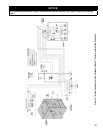
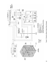
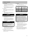
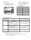
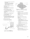
H. Operating Instructions
1. Follow Operating Instructions to place boiler in
operation. See Figure 22.
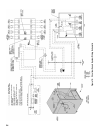
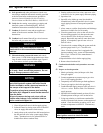
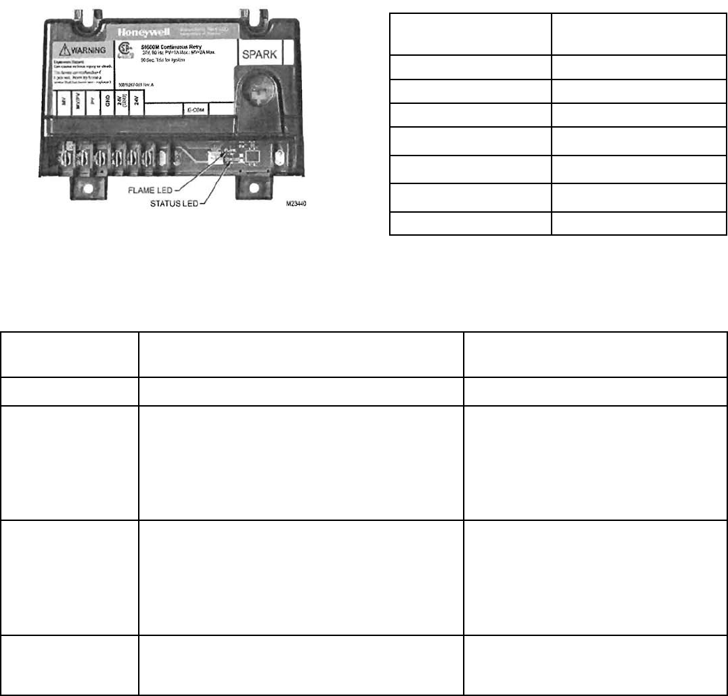
2. Electronic Ignition Modules with LED indicators.
Table 10 cross-references the ignition module
terminal designations to the ignition terminal
Figure 23: LED Locations
Ignition Module
Terminal Designation
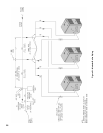
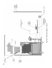
Wiring Ladder Diagram
Terminal Number
MV 1
MV/PV 2
PV 3
GND 4
24V (GND) 5
24V 6
SPARK 9
Table 10: Ignition Module Terminal
Cross-Reference
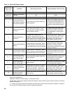
Yellow LED
Flash Code
a
Indicates Recommended Service Action
Heartbeat Normal Flame Signal N/A
2
Weak Flame Signal -
System will operate reliably but ame signal is
less than desired.
Note: This indication may ash temporarily
during or shortly after lightoff on some appli-
cations.
Perform routine maintenance to
assure optimum ame signal.
1
Marginal Flame Signal (less than 1.1 µA) -
System may not operate reliably over time.
Service call recommended.
Note: This indication may ash temporarily
during or shortly after lightoff on some appli-
cations.
Check gas supply, pilot burner, ame
sense wiring, contamination of ame
rod, burner ground connection.
OFF
No Flame or Flame Signal -
Below minimum threshold for system opera-
tion.
N/A
a
Flash Code Descriptions
- Heartbeat: Constant ½ second bright, ½ second dim cycles.
- The ash code number signies that the LED ashes X times at 2Hz, remains off for two
seconds, and then repeats sequence.
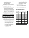
TABLE 11: Yellow LED Flame Codes
numbers in the wiring ladder diagrams. The yellow
LED indicates the status of the ame, see Table 11.
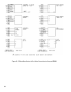
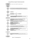
The green LED indicates the status of the system,
see Table 12. See Figure 23 for LED locations. See
Figure 24 for Troubleshooting Guide.