


12
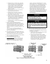
c. Tighten locking band by HAND with a 5/16”
nut driver until snug plus ¼ turn. DO NOT
SECURE JOINTS WITH SHEET METAL
SCREWS OR POP RIVETS. DO NOT
PUNCTURE THE VENT SYSTEM!
d. Once the installation is complete, operate
appliance and inspect all joints to ensure that ue
gases and/or liquid condensate will not escape.
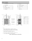
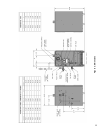
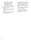
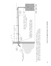
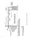
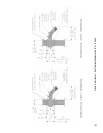
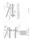
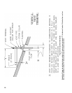
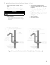
D. Horizontal Venting System. See Figures 4, 4A and 5.
Vent Piping –
1. This boiler is supplied with components as standard
equipment for installation of the separate horizontal
venting system.
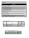
2. Do not exceed maximum vent lengths. Refer to
Table 4.
3. Recommended horizontal installation consists of
vent being sloped down ¼ inch per foot away from
boiler. See Figures 4 and 4A.
4. Use appropriate designed thimbles when passing
through combustible walls (thimble use optional for
noncombustible walls). Insert thimble through wall
from outside. Secure outside ange to wall with
nails or screws, and seal ID, OD and vent holes with
sealant material. Install inside ange to inside wall,
secure with nails or screws, and seal with sealant
material.
5. For noncombustible wall application when thimble
is not used, size opening such that bell with locking
band attached cannot pass through.
6. Join vent terminal to vent pipe. See Figure 5.
7. Insert vent pipe through thimble/opening from
outside and join to vent system. Apply sealant
between vent pipe and opening/thimble to provide
weathertight seal.