


19
SOLID stream without air bubbles for approxi-
mately 10 seconds.
3. Close vent fitting and burner flame should start
immediately.
4. If the burner does not start immediately, check the
manual overload switch on the motor, if so
equipped, and the safety switch on the burner
primary control.
K. ADJUST OIL PRESSURE
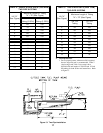
1. Locate oil pressure adjusting screw and turn
screw until Pressure Gauge reads the correct
pump pressure required for the specific boiler.
Refer to Table 4 .
2. DO NOT REMOVE PRESSURE GAUGE until
later.
L. OTHER ADJUSTMENTS
1. ADJUST THE AIR BAND AND/OR AIR SHUT-
TER.
Beckett Burners:
a. Adjust air supply by loosening lock screws and
moving the air shutter and if necessary the air
band. Refer to Table 4 preliminary settings.
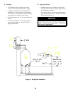
2. ADJUST DRAFT REGULATOR for a draft of
-.02” (water gauge) over the fire after chimney has
reached operating temperature and while burner is
running.
3. READJUST AIR BANDS on burner for a light
orange colored flame while draft over the fire is
-.02” w.c. Use a smoke test and adjust air for
minimum smoke (not to exceed #1) with a mini-
mum of excess air. Make final check using suitable
instrumentation to obtain a CO
2
of 11.5 to 12.5%
with draft of -.02” w.c. in fire box. These settings
will assure a safe and efficient operating condition.
If the flame appears stringy instead of a solid flame,
try another nozzle of the same type. Flame should
be solid and compact. After all adjustments have
been made, recheck for a draft of -.02” w.c. over the
fire.
4. TURN “OFF” BURNER and remove pressure
gauge. Install gauge port plug and tighten. Start
burner again.
M. FLAME FAILURE
The HF boiler controls operate the burner automati-
cally. If for unknown reasons the burner ceases to fire
and the rest button on the primary control has tripped,
the burner has experienced ignition failure. Before
pressing the rest button, call your serviceman immedi-
ately.
N. CHECK FOR CLEAN CUT OFF OF BURNER
1. AIR IN THE OIL LINE between fuel unit and
nozzle will compress when burner is on and will
expand when burner stops, causing oil to squirt
from nozzle at low pressure as burner slows down
and causing nozzle to drip after burner stops.
Usually cycling the burner operation about 5 to 10
times will rid oil line of this air.
2. IF NOZZLE CONTINUES TO DRIP, repeat step
N.1. If this does not stop the dripping, remove cut
off valve and seat, and wipe both with a clean cloth
until clean. Then replace and readjust oil pressure.
If dripping or after burn persist replace fuel pump.
O. HINTS ON COMBUSTION
a. NOZZLES— Although the nozzle is a relatively
inexpensive device, its function is critical to the
successful operation of the oil burner. The
selection of the nozzle supplied with the HF
boiler is the result of extensive testing to obtain
the best flame shape and efficient combustion.
Other brands of the same spray angle and spray
pattern may be used but may not perform at the
expected level of CO
2
and smoke. Nozzles are
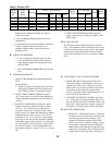
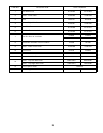
Table 4: Beckett AFG
Boiler
Model
No.
Firing
Rate
(GPH)
Burner
Nozzle Specifications
Static
Plate
Air Settings
Head
Head
Setting
Manufacturer Size Angle Type Shutter Band
HF98 .85 AFG HAGO .75 45° B 3-3/8"U 8 0 L1 0
HF122 1.10 AFG HAGO .90 45° B 3-3/8"U 10 2 L1 0
HF147 1.25 AFG HAGO 1.0 45° B 2-3/4"U 10 0 V1 0
HF173 1.50 AFG HAGO 1.25 45° B 2-3/4"U 10 2 V1 2