


12
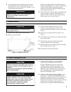
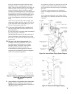
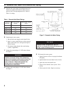
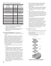
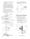
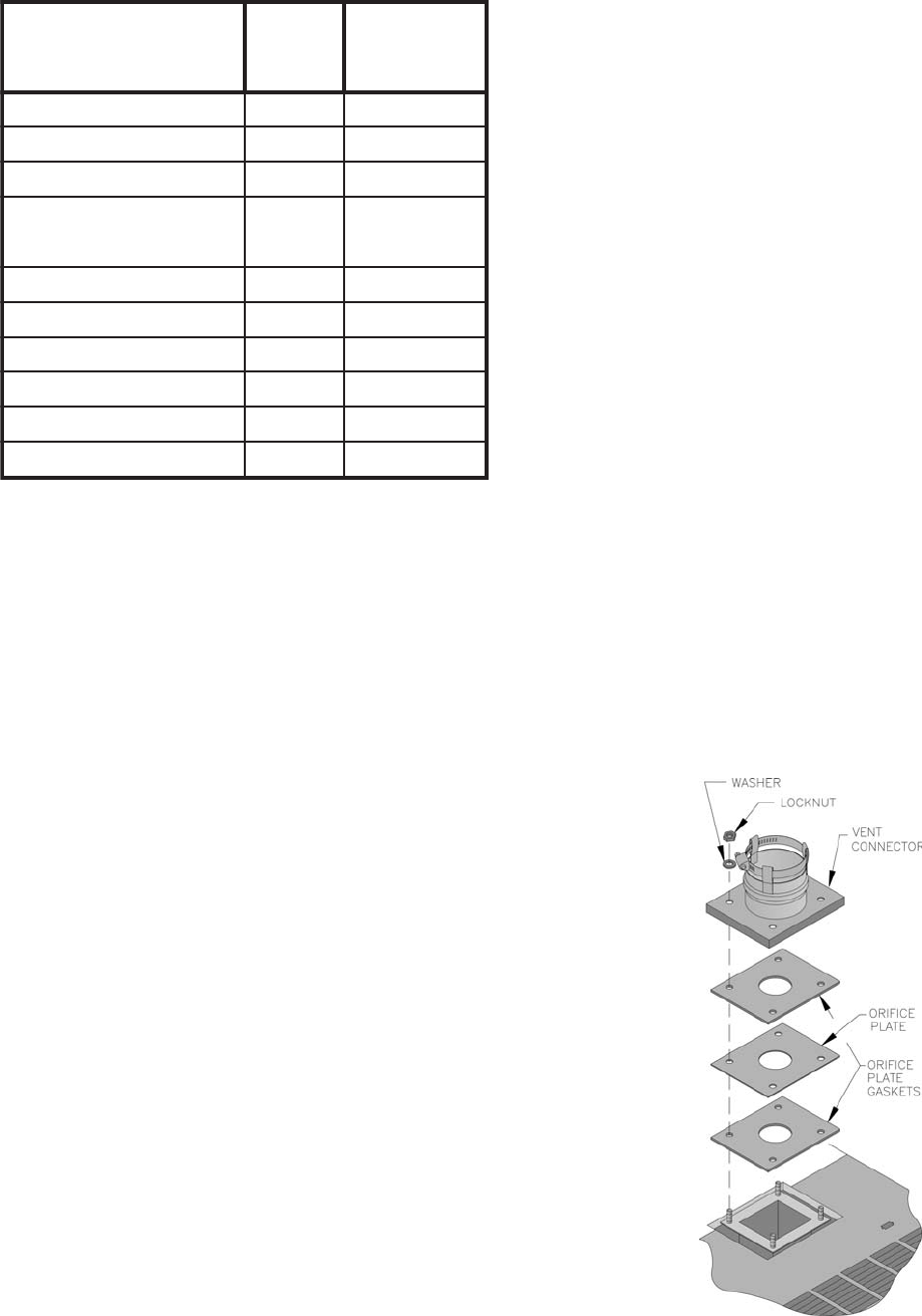
Figure 9: Vent Connector Installation
4. Do not install venting system components on the
exterior of the building except as specifi cally
required by these instructions.
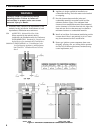
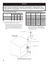
5. Thickness of exterior walls through which vent-air
intake system may be installed: Minimum: 3",
Maximum: 12".
B. Removal of Existing Boiler. For installations not
involving the replacement of an existing boiler, proceed
to Step C.
When an existing boiler is removed from a common
venting system, the common venting system is likely to
be too large for proper venting of the remaining
appliances. At the time of removal of an existing boiler,
the following steps shall be followed with each
appliance remaining connected to the common venting
system placed in operation, while the other appliances
remaining connected to the common venting system
are not in operation:
1. Seal any unused openings in the common venting
system.
2. Visually inspect the venting system for proper size
and horizontal pitch and determine there is no
blockage or restriction, leakage, corrosion, and other
defi ciencies which could cause an unsafe condition.
3. Insofar as is practical, close all building doors and
windows and all doors between the space in which
the appliances remaining connected to the common
venting system are located and other spaces of the
building. Turn on clothes dryers and any appliance
not connected to the common venting system. Turn
on any exhaust fans, such as range-hoods and
bathroom exhausts, so they will operate at maxi mum
speed. Do not operate a summer exhaust fan. Close
fi replace dampers.
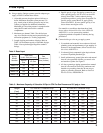
Table 7: Burnham Vent System Components
4. Place in operation the appliance being inspected.
Follow the Lighting (or Operating) Instructions.
Adjust thermo stat so appliance will operate
continuously.
5. Test for spillage at the drafthood relief opening after
5 minutes of main burner operation. Use the fl ame
of a match or candle, or smoke from a cigarette,
cigar or pipe.
6. After it has been determined that each appliance
remain ing connected to the common venting system
properly vents when tested as outlined above, return
doors, win dows, exhaust fans, fi replace dampers and
any other gas burning appliance to their previous
conditions of use.
7. Any improper operation of the common venting
system should be corrected so the installation
conforms with the National Fuel Gas Code,
ANSI Z223.1 and/or CAN/CGA B149, Installation
Codes. When resizing any portion of the common
venting system, the common venting system
should be resized to approach the minimum size as
determined using the appropriate tables in Part 11 in
the National Fuel Gas Code, ANSI Z223.1 and/or
CAN/CGA B149, Installation Codes.
C. Install Vent Connector.
1. Remove vent connector from vent accessory carton.
2. Remove gaskets, orifi ce plate and hardware from
blower outlet fl ange.
3. Assemble orifi ce plate gaskets, orifi ce plate, and
vent connector. See Figure 9.
mahnruB
metsyStneV
tnenopmoC
mahnruB
traP
rebmuN
tnelaviuqE
epiPfoteeF
tF1xepiP.aiD"3U69261181
tF3xepiP.aiD"3U89261183
tF5xepiP.aiD"3U00361185
elbatsujdAxepiP.aiD"3U9136118
otlauqE
htg
neLdellatsnI
)46.1ot60.1(
woblE°09.aiD"3U49261185
woblE°54.aiD"3U29261185
eeTniarDlatnoziroH.aiD"3U2036118½
eeTn
iarDlacitreV.aiD"3U4036118½7
elbmihTllaWelgniS"36116118---
elbmihTllaWelbuoD"35116118---