


31
SOLID stream without air bubbles for approxi-
mately 10 seconds.
3. Close vent fitting and burner flame should start
immediately.
4. If the burner does not start immediately, check the
manual overload switch on the motor, if so
equipped, and the safety switch on the burner
primary control.
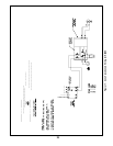
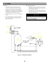
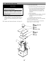
K. ADJUST OIL PRESSURE
1. Locate oil pressure adjusting screw and turn
screw until Pressure Gauge reads the correct
pump pressure required for the specific boiler.
Refer to table 4 & 4A.
2. DO NOT REMOVE PRESSURE GAUGE until
later.
L. OTHER ADJUSTMENTS
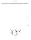
1. ADJUST THE AIR BAND AND/OR AIR SHUT-
TER.
Beckett Burners:
a. Adjust air supply by loosening lock screws and
moving the air shutter and if necessary the air
band. Refer to Table 4 and 4A preliminary
settings.
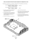
2. ADJUST DRAFT REGULATOR for a draft of
-.02” (water gauge) over the fire after chimney has
reached operating temperature and while burner is
running.
3. READJUST AIR BANDS on burner for a light
orange colored flame while draft over the fire is
-.02” w.c. Use a smoke test and adjust air for
minimum smoke (not to exceed #1) with a mini-
mum of excess air. Make final check using suitable
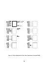
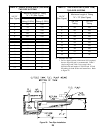
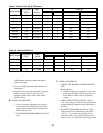
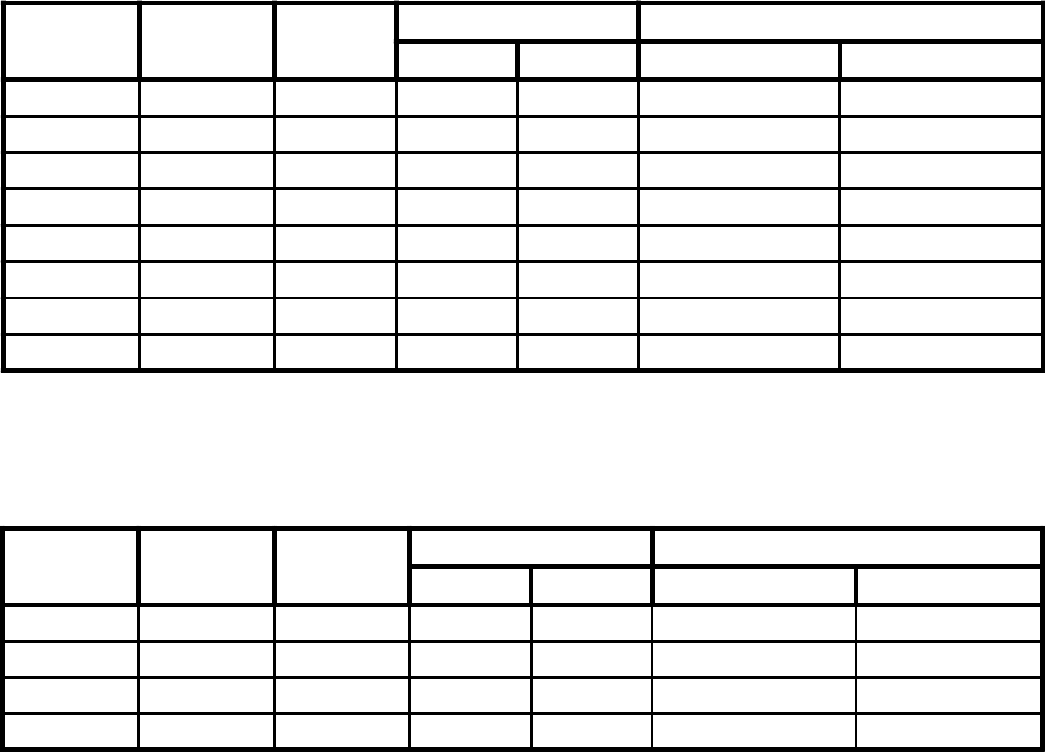
Table 4A: Becket AFG Burner
Table 4: Beckett AFG, AF, & SF Burners
Boiler Model
Firing Rate
(GPH)
Hago
Nozzle
Air Settings
Shutter Band Head (stop screw) Pump Pressure
RSAH85 .75 .65 x 80B 6 0 N/A 140
RSAH110 1.0 .85 x 80B 7 0 N/A 140
RSAH125 1.1 .90 x 80B 7 0 N/A 140
RSAH135 1.25 1.0 x 80B 9 0 N/A 140
Boiler Model
Firing Rate
(GPH)
Hago
Nozzle
Air Settings
Shutter Band Head (stop screw) Pump Pressure
RSA85 .85 .75 x 70B 10 0 N/A 140
RSA110 1.10 .90 x 80B 8 0 N/A 140
RSA125 1.25 1.0 x 80B 7 0 N/A 140
RSA135 1.35 1.10 x 80B 9 0 N/A 140
RSA170 1.70 1.65 80 A 7 0 N/A 100
RSA195 1.95 2.00 80 B 7 0 N/A 100
RSA240 2.40 2.50 80 B 7 0 N/A 100
RSA285 2.85 3.00 80 B 7 0 N/A 100