


11
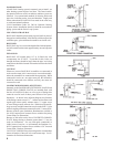
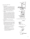
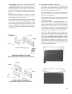
Stand Assemblies upright, place in position and fasten to the
walls with Top Center Supports using the number shown in the
table above. Insert Top Center Supports in Air Outlet opening
of Sections opposite studs (stud locations determined in step
1). Use wood screw furnished with Top Center Support and
screw into stud until tight, the longer dimension of the top
center support is in a vertical position when installed. Back
off fraction of a turn to permit movement caused by expansion
and contractions of sections. Adjust Bottom Center Supports
by turning Cap Screws down until they begin to contact À oor.
Do not extend the Cap Screws any further.
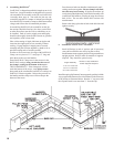
Connect assemblies to piping. Complete remainder of piping
to boiler, ¿ ll system with water and check for leaks.
CARE MUST BE EXERCISED TO SEE THAT 30 PSI GAUGE
PRESSURE IS NOT EXCEEDED.
DO NOT PRESSURE TEST WITH AIR.
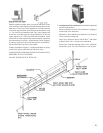
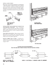
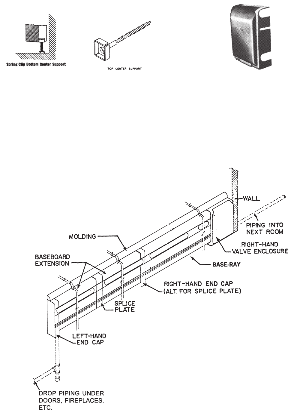
7. Installation of Valve enclosures (furnished in right-hand
and left-hand patterns).
Remove knockout in end of Valve Enclosure if piping to
run through Valve Enclosure.
Bend tab on Valve Enclosure so that hole is on inside of
Valve Enclosure facing wall.
Place Valve Enclosure next to BASE-RAY
®
and fasten
to BASE-RAY with ¼” thumb screw furnished.
Insert screw furnished through tab on Valve Enclosure
and fasten to wall. Set Valve Enclosure Cover in place.