


10
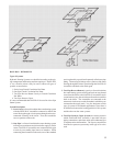
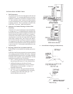
5. Assembling BASE-RAY
®
BASE-RAY is shipped assembled in lengths up to six (6)
lineal feet – longer assemblies are shipped in two or more
sub-assemblies for assembly on the job (see BASE-RAY
Assembly chart, page 4). One man can join tow sub-
assemblies together in a matter of minutes providing he
has a BASE-RAY Assembly Clamp (available at a nominal
charge) and follows the recommended procedure.
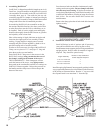
In assembling BASE-RAY sub-assemblies on the job,
the sections should be lined up, face down, on the À oor
or other À at surface near the wall on which they are to
be installed. Ends of section, nipple ports and nipples
should be thoroughly cleaned with kerosene or gasoline
and wiped dry with a clean cloth.
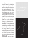
Place a thin coating of nipple lubricant on nipples and
insert into the nipple ports of one assembly without
cocking. Engage nipples in nipple ports of second
assembly and push sections together by hand as far as
possible keeping ends of sections parallel.
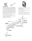
In order to secure necessary leverage with BASE-RAY
Clamp, cut two pieces of 1¼” steel pipe 15” long and
place them on the two cam handles.
Insert BASE-RAY Clamp nose in the recesses in the
BASE-RAY castings, being certain that the nose of
the clamp is resting on the bottom of the recess –
THIS IS IMPORTANT. If the clamp nose will not
reach the bottom of the recess, exert light pressure
downward on the cam handles until the two castings are
PARTIALLY drawn together. Release the pressure on
the handles and the clamp nose will then drop to the
bottom of the recess.
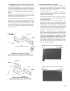
Press down on both cam handles simultaneously until
castings are drawn together. Be sure clamp is not tilted,
since this may break casting. If nipples do not draw up
evenly during ¿ nal tightening, strike end of assembly with
wood block and hammer or mallet to bring the sections
back in line. Do not strike BASE-RAY sections with
metal hammer.
Remove the clamp, place the tie bolts in the bolt slots and
tighten securely.
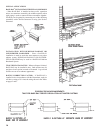
6. Installation of BASE-RAY
®
Assemblies
Install all ¿ ttings in end of sections and all necessary
vents while assemblies are still laying À at on À oor.
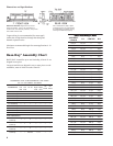
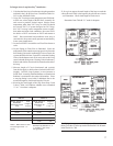
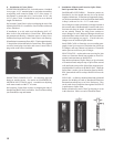
Install bottom center supports prior to raising assemblies to
upright position. Refer to table for number of supports
required. They should be spaced evenly.
ylbmessAhtgneL
mottoBdnapoTforebmuN
deriuqeRstroppuSretneC
teeFlaeniL½41ot½11
teeFlaeniL½12ot512
teeFlaeniL½82ot223
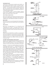
Install the spring clip Bottom Center support by pushing it all the
way up against the bottom of two ¿ ns and next to the waterway
of the section as illustrated below. Run the ¼” cap screw into
the clip until head is not more than ¾” from the clip.