


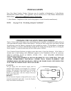
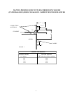
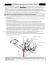
OPTIONAL BLOWER INSTALLATION
The Model 42ZCBB has an optional MA ZCBB714 blower kit that can be purchased from your
dealer. You will need to follow these steps and the diagram below and the wiring diagram on page 15.
NOTE: The receptacle which is provided in the Model 42ZCBB must be wired into your home
(residence) in order to have electricity to operate the blower motor. If the receptacle hasn’t been
wired in during installation of the 42ZCBB you may need to contact a licensed electrician. The Model
42ZCBB also has a thermostat and wires and an ON/OFF switch standard on all units.
“WARNING: Any changes to this heater or its controls can be dangerous.”
A. First remove the burner base and logs. Be sure to turn “OFF” the gas supply before disconnecting
the supply line.
B. Remove the (10) ten hex-head self-piercing screws that hold down the motor cover plate on the
inner bottom of the unit.
C. Locate the (2) two wires that come down the back of the rear air channel from the thermo-
stat .Connect (1) one of the thermostat wires to the top terminal on the ON/OFF switch.
D. Connect the black power cord wire to the 24" jumper wire provided, then attach the jumper wire
to the middle terminal on the ON/OFF switch. Next connect the remaining thermostat wire to (1)
of the wires coming from the motor. Connect the white power cord wire to the white motor wire.
The green power cord wire should be screwed to the motor bracket as the ground wire. Place the
blower motor in the cover plate opening. Position the blower motor into the air channel on the rear
of the unit centering the blower motor. It is best to leave about a 1/8" space between the blower
and the back of the air channel. This will reduce the chance of vibrating or noise.
E. After placing the blower motor you must secure it to the bottom of the unit with the (2) two
#10x1/2 Hex Washer Head self-piercing screws provided with the blower kit.
F. Plug the power cord into the receptacle, and reattach the motor cover plate to the inner bottom us-
ing the screws you removed earlier.
NEW R
E
DATE
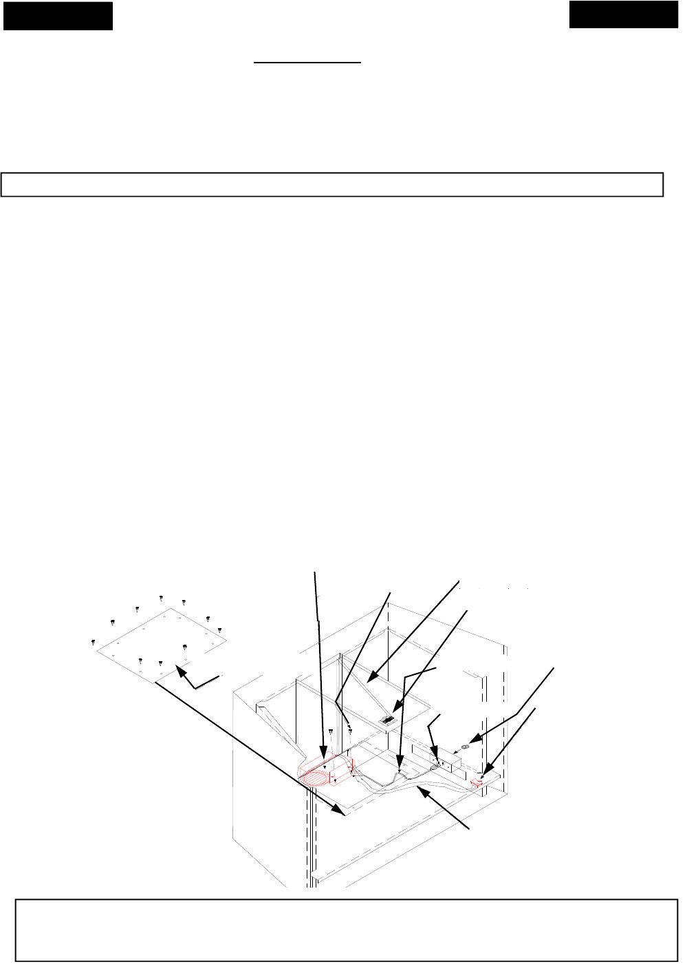
BLOWER MOTOR
MOTOR COVER PLATE
SCREWS
POWER CORD
RECEPTACLE ON / OFF SWITCH
WIRES TO
SWITCH
SCREWS
ROMAX CONNECTOR
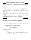
WARNING: IF THE INFORMATION IN THIS MANUAL IS NOT FOLLOWED EXACTLY, A
FIRE OR EXPLOSION MAY RESULT CAUSING PROPERTY DAMAGE, PERSONAL INJURY
OR LOSS OF LIFE.
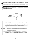
THERMOSTAT
THERMOSTAT WIRES
17