


14
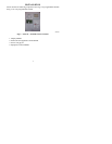
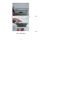
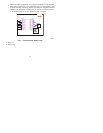
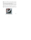
6. Match and connect equipment wires to proper terminals of each connector
block being careful not to over tighten the screws. Correct polarity must
be observed when connecting the two wires from the Equipment Control
Module to the thermostat mounting base. If wires are connected incorrect-
ly, the Display Module will not operate. See Fig. 7, 8 and 9.
Relays
OAT
RRS
SRTN
HUM
D1
D2
V+
Vg
Rc
Rh
W / W1
G
Y/Y2
Y used for
single stage
cooling
C
O/W2/B
Y1
Y1 used for
multi-speed
cooling
Y1 = stage 1
Y2 = stage 2
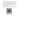
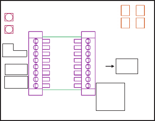
Control Module Wiring Guide
connect
to user
interface
dry
contact
OAT /
RRS
return
{
Relays
OAT
RRS
SRTN
HUM
D1
D2
V+
Vg
Rc
Rh
W / W1
G
Y/Y2
Y used for
single stage
cooling
C
O/W2/B
Y1
Y1 used for
multi-speed
cooling
Y1 = stage 1
Y2 = stage 2
Control Module Wiring Guide
connect
to user
interface
dry
contact
OAT /
RRS
return
{
A07687
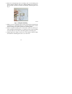
Fig. 7 -- Control Module Wiring Guide
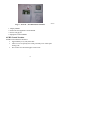
S Red is V+
S Black is Vg