


8
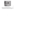
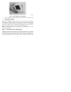
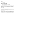
7. Adjust length and routing of each wire to reach proper terminal and con -
nector block on mounting base with 1/4-- in. (6 mm) of extra wire. Strip only
1/4 in. of insulation from each wire to prevent adjacent wires from shorting
together when connected. See Fig. 2.
A07155
Fig. 2 -- Secure Wires to Terminal Strip
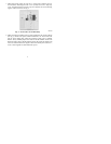
8. Mat ch and connect equipment wir es to proper ter mi nal s of t he connector blocks
(see Fig. 3). If there ar e separate 24VAC trans f or mer s, one in the indoor unit
and one in t he outdoor unit, connect t he common of each t o the C t er mi nal .
Remove factory--instal l ed jumper wir e from Rc and R h ter mi nal s . Connect the
R f r om the indoor unit to the R h ter mi nal. Connect the R from t he outdoor unit
to the Rc terminal . T hen the W signal is taken f r om the R h power and the Y1,
Y/Y 2, G and O signal s are t aken f r om the R c pow er.