


3
Available Selection:
Use UP and DOWN buttons to change between H and C.
Option 13 — Room Temperature Offset Adjustment
This option allows calibration (or deliberate miscalibration) of the
room temperature sensor. There are various reasons why
homeowners may want to have displayed temperature adjusted to a
higher or lower value. The selected number is the number of
degrees, plus or minus, which will be added to actual temperature.
The numbers can range between --5 and +5. Factory default is 0.
Available Selection:
Use UP and DOWN buttons to now move between --5 and +5 in
increments of 1.
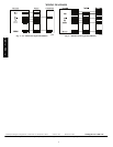
Step 4 — Thermostat Operation
Temperature Display
Thermostat will display room temperature until UP or DOWN
button is pressed. The word SET appears when these buttons are
pressed and the current setpoint is displayed. If no buttons are
pressed for 5 sec, the display will change back to show room
temperature.
Timeguard Timer
A 5--minute timeguard is built into the thermostat immediately
upon power up, and any time the compressor turns off. The
compressor will not turn on until the timeguard has expired. The
timeguard affects only compressor operation. Pressing UP and
FAN buttons simultaneously will override the timeguard for 1
cycle. With PH or PC selected under Option 01, this timer is
defeated.
Cycle Timer
In normal heating and cooling operation the thermostat will not
allow more than 4 equipment cycles per hour (or 1 cycle every 15
minutes). Both the Y and W outputs have a 15--minute timer that
starts counting down when the output is turned on, (e.g., if Y
output is turned on for 9 minutes and then satisfies, it cannot turn
back on for another 6 minutes regardless of demand). However,
pressing UP and FAN buttons simultaneously or changing the
setpoint will override the timer for 1 cycle.
Minimum on Timer
Once the equipment has turned on, it will remain on for a
minimum of 3 minutes regardless of demand. However, the
equipment can turn off in less than 3 minutes if a change in
setpoint or a change in mode occurs.
Staging Timer
If the thermostat is a heat pump model, it has 2--stage heat
capability. With HP operation, there is a 15--minute delay between
the first and second stages of heat. The Y output will energize first,
then 15 minutes later, W is allowe d to come on if the thermostat
determines it is not satisfying the demand.
However, if the heating demand is greater than 5_F, there will be
only a 30 second delay before bringing on W.
Auxiliary Heat Indicator
A green LED indicates the use of auxiliary heat or emergency heat.
Error Messages
“-- --” (two dashes) will be displayed if the thermostat cannot
properly read room temperature. If “----” appears, replace
thermostat.
E4 will be displayed if the thermostat has an internal memory
failure. If E4 appears, replace thermostat.
Step 5 — Check Thermostat Operation
Fan Operation
1. Press FAN button. This will start continuous fan operation.
FAN annunciator will turn on.
2. Press FAN button again. This will stop continuous fan
operation. FAN annunciator will turn off.
Heating Operation
1. Press H/C button until HEAT is displayed.
2. Press UP button until LCD readout reads 3_F above room
temperature. Press UP and FAN buttons simultaneously to
defeat timers. Heating system should begin to operate
imme diately .
3. For HP thermostats only, press H/C button until EMHT
(emergency heat) appears. Pr ess UP and FAN buttons
simultaneously to defeat timers. Emer gency heating (W is
ON, Y is OFF) should begin immediately.
Cooling Operation
1. Press H/C button until COOL is displaye d.
2. Press DOWN button until LCD readout reads 3_Fbelow
room temperature. Press UP and FAN buttons
simultaneously to defeat timers. Cooling system should
begin to operate immediately.
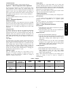
Table 1 shows the thermostat outputs for each available stage of
heating or cooling. It may be useful in checkout or
troubleshooting.
Table 1 – Outputs
EQUIPMENT
CONFIGURATION
OPTION #1
THERMOSTAT
FACTORY
CONFIGURATION
COOL
STAGE 1
HEAT
STAGE 1
HEAT
STAGE 2
EM HEAT
AC, PC AC, HP Y, G W --- --- --- ---
HP, PH
RVS = C
HP Y, G, O/B Y, G Y, G, W W
HP, PH
RVS = H
HP Y, G Y, G, O/B Y, G, W, O/B W
T1--NAC / T1--NHP