


2
Step 2 — Install Thermostat
ELECTRICAL SHOCK HAZARD
Failure to follow this warning could result in personal injury
or death.
Before installing thermostat, turn off all power to unit. There
may be more than 1 disconnect.
!
WARNING
1. Turn OFF all power to unit.
2. If an existing thermostat is being replaced:
a. Re move existing thermostat from wall.
b. Disconnect wires from existing thermostat, one at a
time. Be careful not to allow wires to fall back into wall.
c. As each wire is disconnected, record wire color and
terminal marking.
d. Discard or recycle old thermostat.
ENVIRONMENTAL HAZARD
Failure to follow this caution may result in environmental
damage.
Mercury is a hazardous waste. Federal regulations require that
Mercury be disposed of properly.
CAUTION
!
3. Separate front and back (mounting base) assembly of
thermostat.
4. Route thermostat wires through hole in mounting base.
Level mounting base against wall (for aesthetic value only,
thermostat need not be level for proper operation) and mark
wall through 2 mounting holes.
5. Drill two 3/16--i n. mounting holes in wall where marked.
6. Secure mounting base to wall with 2 anchors and screws
provided making sure all wires extend through hole in
plastic.
7. Strip 1/4 in. insulation from thermostat wire and adjust
length to reach terminal block connector on mounting base.
Match and connect proper wiring in accordance with wiring
diagrams.
8. Push any excess wire back into wall. Seal hole in wall to
prevent air leaks. Leaks can affect thermostat operation.
Any excess wire left inside thermostat casing may also
affect thermostat operation by interfering with airflow
across the temperature sensor.
9. Snap thermostat together making sure terminal block
connector aligns, and assembly is secure.
10. Turn on power to unit.
On power up, depending on the thermostat model being used, the
LCD readout will display either, AC or PC for air conditioner
model (1-- stage heat/1--stage cool), or HP or PH for heat pump
model (2 --stage heat/1--stage cool).
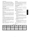
Step 3 — Set Thermostat Configuration
Configuration options allow the installer to configure the
thermostat for a particular installation. These selections are
intended to be made at installation and normally are not modified
by the homeowner. Below is a list of available options followed by
a description of each one.
Option 01 -- Equipment Type
Option 03 -- Fahrenheit or Centigrade operation
Option 04 -- Enable fan (G) ON with heat (W)
Option 10 -- O (reversing valve) On with Heat or Cool (present
on Heat Pump model only)
Option 13 -- Room temperature offset adjustment
Note that not all configuration option numbers are used in this
product.
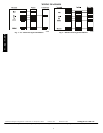
To Enter The Configuration Mode:
Press and hold FAN button for approximately 10 sec until room
temperature disappears and the display reads “01”. You are now in
configuration mode.
NOTE: If FAN button is pressed again, or if no button is pressed
for 3 minutes, the thermostat will exit configuration mode and
return to normal operation. To re--enter configuration mode, the
FAN button must be pressed and held for 10 sec again.
While in the conf iguration mode, the temperature display is used to
show both the option number and the selected choice within each
option. Each press of the H/C button alternates between the option
number and the selection within that option. When the
configuration mode is first entered, option 01 is displayed. The up
and down buttons now move between the available option
numbers. Once an option number is selected, press the H/C button
once to displ ay the currently selected choice within that option.
The up and down buttons now move between the available choices
within that option. After the new c hoice is made, press the H/C
button again to return to the option numbe r display. Whe n finished
with option selections, press FAN button once to exit the
configuration mode.
Option 01 — Equipment Type
Selections: with HP thermostat: HP, AC, PH, or PC
with AC thermostat: AC or PC
Meanings:
PH or PC selects PTAC units (Packaged Terminal Air
Conditioners) which are used in motel rooms and other
rented spaces. When this option is selected, the display
shows only the setpoint, not the room temperature. Also
the compressor timeguard is disabled, allowing the
compressortoturnonimmediatelywhenademandis
established.
HP or PH controls 1 speed heat pump with 1 stage of aux heat.
AC or PC controls 1 speed air conditioner with one stage of heat.
Note that this option allows a HP thermostat to be converted to
control an AC system.
Option 03 — Fahrenheit/Centigrade Selection
This selection operates the thermostat in either Fahrenheit or
Centigrade. Factory default is F.
Available Selection:
Use UP and DOWN buttons to change between F and C.
Option 04 — G (fan) ON with W (Heat) Selection
This selection determines whether G (fan) output is to be ON or
OFF when W (furnace or strip heat) output is ON. Most furnaces
and fan coils manage their own blowers and do not require a
separate G signal. For these applications, select OFF. Some
auxiliary heaters require a separate G signal from the thermostat to
turn on the blower. In this case, select ON. Factory default is OF
(off).
Available Selection:
Use UP and DOWN buttons to change between ON an d OFF.
Option 10 — O (reversing valve) On with Heat or Cool
Selection
This selection is only available on heat pump model thermostats.
This selection determines whether the reversing valve is energized
in the heating or cooling mode. Factory default is C.
T1--NAC / T1--NHP