T874 MULTISTAGE THERMOSTATS AND Q674 SUBBASES
7 60-2485—8
MERCURY NOTICE
This control contains mercur
y
in a sealed tube. Do
not
place control in the trash at the end of its useful life.
If this control is replacin
g
a control that contains
mercur
y
in a sealed tube, do
not
place
y
our old control
in the trash.
Contact
y
our local waste mana
g
ement authorit
y
for
instructions re
g
ardin
g
rec
y
clin
g
and the proper
disposal of this control, or of an old control containin
g
mercur
y
in a sealed tube. If
y
ou have
q
uestions, call
the Hone
y
well Customer Response Center at
1-800-468-1502.
INSTALLATION
When Installing this Product…
1.
Read these instructions carefull
y
. Failure to follow them
could dama
g
e the product or cause a hazardous condi-
tion.
2.
Check the ratin
g
s
g
iven on the product to make sure the
product is suitable for
y
our application.
3.
Installer must be a trained, experienced service techni-
cian.
4.
After installation is complete, check out product opera-
tion as provided in these instructions.
CAUTION
Hazardous Voltage.
Can damage heating/cooling system.
1. Disconnect power suppl
y
before be
g
innin
g
instal-
lation to prevent electrical shock or e
q
uipment
dama
g
e.
2. Do
not
short across coil terminals on rela
y
. This
can burn out thermostat heat anticipator.
3. To prevent interference with the thermostat link-
a
g
e, keep wire len
g
th to a minimum and run wires
as close as possible to the subbase.
4. Do
not
overti
g
hten thermostat captive mountin
g
screws because dama
g
e to subbase threads can
result.
IMPORTANT
An incorrectly leveled thermostat will cause the tem-
perature control to deviate from setpoint. It is not a
calibration problem.
Location
Install the thermostat about 5 ft
(
1.5m
)
above the floor in an
area with
g
ood air circulation at avera
g
e temperature.
Do not mount the thermostat where it can be affected b
y
:
— drafts or dead spots behind doors, in corners or under
cabinets.
— hot or cold air from ducts.
— radiant heat from the sun, fireplace, or appliances.
— concealed pipes and chimne
y
s.
— unheated
(
uncooled
)
areas such as an outside wall behind
the thermostat.
Mount Subbase
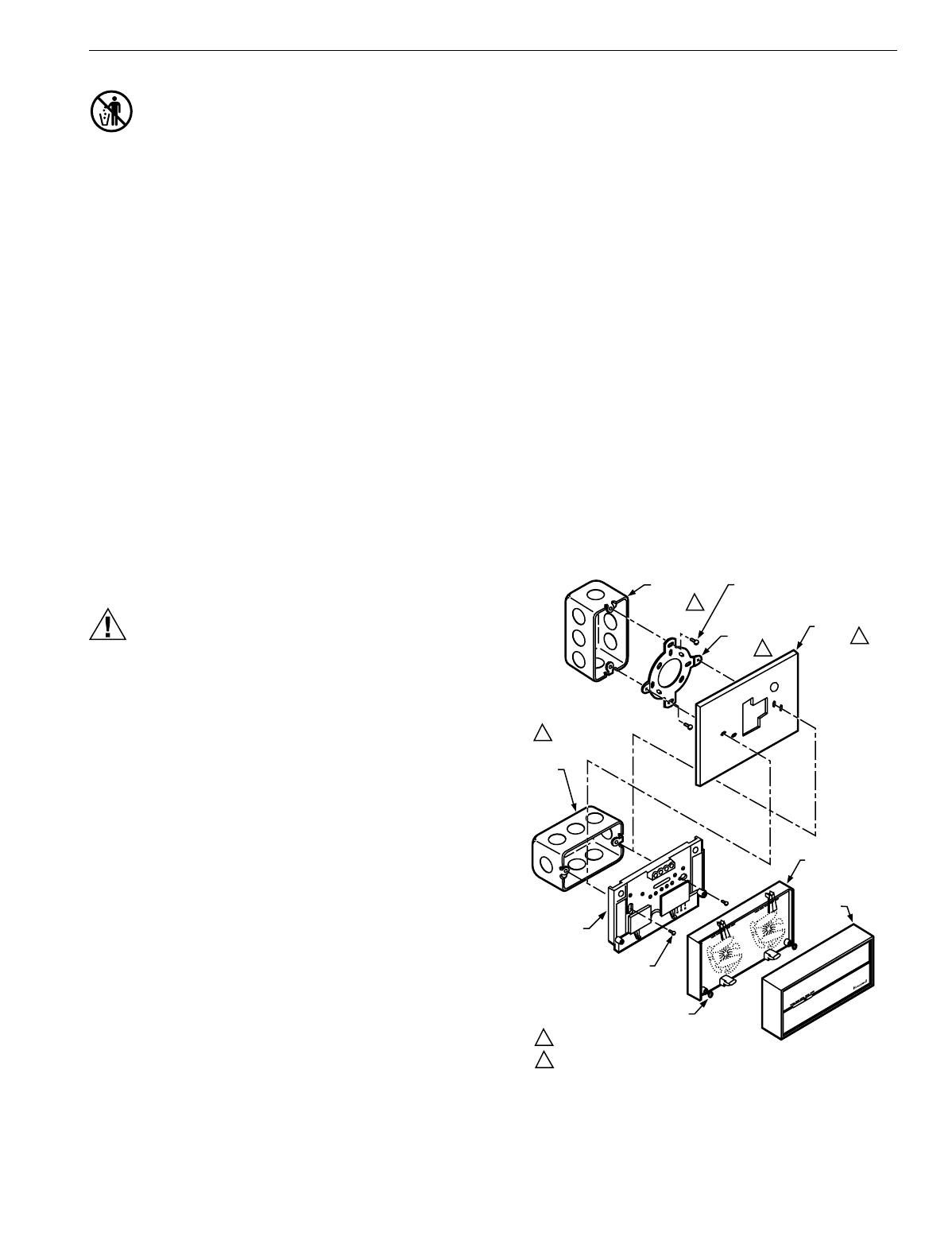
The subbase can be mounted on a vertical outlet box,
horizontal outlet box or directl
y
on the wall.
1.
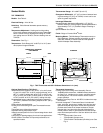
If the subbase is mounted on a vertical outlet box, order
Hone
y
well part no. 193121A Adapter Assembl
y
. See
Fi
g
. 4. The assembl
y
includes an adapter rin
g
, two
screws and a cover plate to cover marks on the wall.
Install the rin
g
and cover plate on the vertical outlet box.
NOTE: For a wall installation, hold subbase in position and
mark holes for anchors. See Fi
g
. 5. Wall anchors
must be obtained from local hardware store. Be
careful that the wires do not fall back into the wall
openin
g
. Set aside subbase. Drill four
3/16 in.
(
4.8 mm
)
holes and
g
entl
y
tap anchors into
the holes until flush with the wall.
2.
Pull wires throu
g
h the cover plate
(
if used
)
and subbase
cable openin
g
. See Fi
g
. 6.
3.
Secure the cover plate
(
if used
)
and subbase with the
screws provided. Do not full
y
ti
g
hten the subbase
screws.
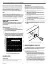
Level the subbase usin
g
a spirit level, see Fi
g
. 7, and firml
y
ti
g
hten subbase mountin
g
screws. The subbase mountin
g
holes provide for minor out-of-level ad
j
ustments.
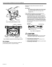
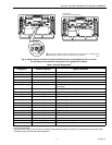
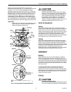
Fig. 4. Installing Q674 Subbase on outlet box.
M6009
VERTICAL
OUTLET
BOX
ADAPTER
RING
COVER
PLATE
MOUNTING
SCREWS (2)
1
SUBBASE
SUBBASE
MOUNTING SCREWS (2)
HORIZONTAL
OUTLET
BOX
1
2
2
1 NOT INCLUDED WITH UNIT.
2 ACCESSORY PART AVAILABLE (193121A).
THERMOSTAT
CAPTIVE
MOUNTING SCREWS (2)
5
0
6
0
7
0
8
0
5
0
6
0
7
0
8
0
H
E
A
T
C
O
O
L
THERMOSTAT
COVER
5
0
6
0
7
0
8
0


