


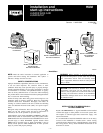
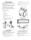
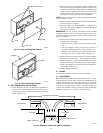
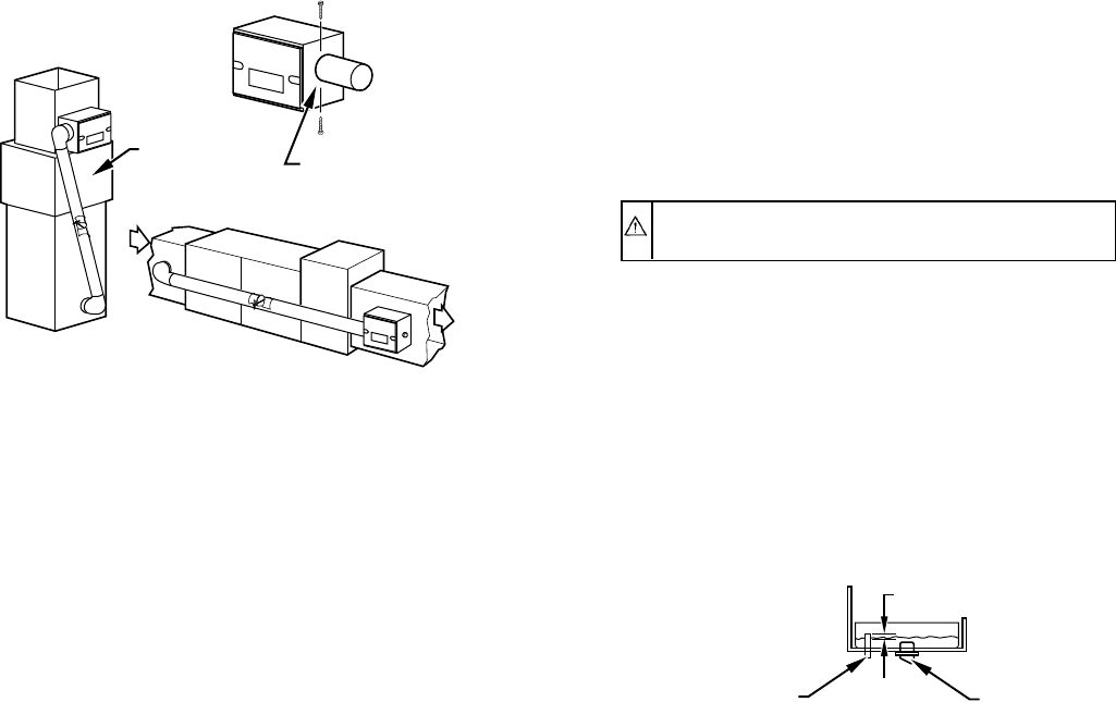
II. SELECT LOCATION (SEE FIG. 14.)
Humidifier may be installed on either supply or return plenum. If
furnace has air conditioning coil, be sure humidifier does not
interfere with coil ends. Remember to provide clearance for
maintenance and evaporator pad removal.
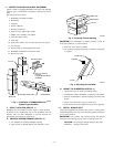
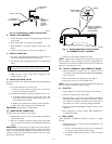
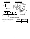
III. PREPARE PLENUM OPENING (SEE FIG. 2.)
1. Use template for marking humidifier opening.
2. Tape in place on plenum making sure template is level.
IMPORTANT: For humidifier to operate properly it must be
level and mounted on a vertical surface.
3. Drill four 1/8-in. holes in plenum.
4. Cut opening in plenum using heavy solid lines on template
as a guide.
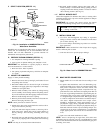
IV. MOUNT THE HUMIDIFIER
Supply or return plenum mounting:
1. Remove unit access door by turning 2 pawl latches 1/2 turn
and pulling door forward.
2. Determine whether unit is to be used for right- or left-hand
installation and apply gasket tape (supplied) to unit flange
intended to seat against duct.
3. Remove media assembly from cabinet by lifting bearing
end of assembly out of bearing retainer and pulling assem-
bly toward outlet duct, thus disengaging media from motor.
Remove media through unit access opening.
4. Remove pin from float assembly and remove float and arm.
Remove drain plug and water pan.
NOTE: Water pan must be tilted for removal.
5. Mount unit to duct using pre-drilled holes and four 1/2-in.
long screws found in parts bag.
6. Level unit and attach support bracket to unit using 1/4-in.
blunt point screw. Attach other end of support bracket to
duct by drilling a hole and using remaining 1/4-in. long
screw.
7. Re-install water pan and drain plug. Re-attach float arm to
valve body by aligning holes in both parts and re-inserting
pin.
NOTE: Pin may be re-inserted from either direction.
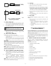
8. Re-install media assembly. Ensure that square shaft of
media assembly is located inside mating opening of motor
coupling. Ensure that bearing washer is located on interior
side of bearing retainer. (See Fig. 15.)
V. INSTALL BYPASS DUCT
Attach field-supplied 6-in. diameter duct, elbow, or starting collar
with field-supplied 1/4-in. zip screws. Install supplied 6-in. damper
in 6-in. duct connector.
IMPORTANT: On systems with central cooling, the damper
should be closed during cooling season to prevent bypass air.
CAUTION: Do not support weight of duct from humidi-
fier — damage could result.
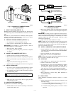
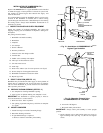
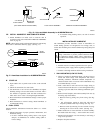
VI. INSTALL DRAIN LINE
1. Use 1/2-in. ID field-supplied vinyl tubing or equivalent
tubing to connect overflow drain connection on unit water
pan to drain. (See Fig. 16.)
2. Use worm clamp to hold tubing in position over overflow
drain connection.
IMPORTANT: Make sure that line is free of traps due to sagging
and has sufficient pitch to drain.
3. Unit must be level to provide proper drainage.
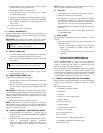
VII. MAKE WATER CONNECTION
1. Mount saddle valve on cold water line according to local
codes.
2. For plastic tube installations: run 1/4-in. OD tubing (sup-
plied) from saddle valve to float valve. Prepare tubing ends
with plastic compression sleeves and brass inserts, and
tighten compression fittings. Plastic compression nut sup-
plied with float valve should not be torqued greater than 25
in.-lb. For copper tubing installations: copper tubing may be
connected to float valve by using a field-supplied 1/4 to 1/4
in. straight-through compression union. Run copper tubing
to 1 side of compression union and use a standard compres-
sion sleeve. Tighten compression nut to torque recom-
mended by manufacturer. Attach approximately 6 in. of
polyethylene supply tubing (supplied) between compres-
sion union and float valve. Prepare polyethylene tubing on
both ends with brass inserts to prevent tubing collapse. Use
compression nut at union to manufacturer’s recommended
torque, tighten plastic nut on float valve to maximum of 25
in.-lb.
3. Open valve and check installation for leaks.
NOTE: Valve is self piercing on copper lines; 1/4-in. hole must
be drilled in steel or iron pipes. Use only a grounded drill or a hand
drill to avoid shock hazard. Turn off water and drain the pipe prior
to drilling 1/4-in. hole.
→ Fig. 14—Installation of HUMBBWTR2019-A--
Water Saver Humidifier
A98369
VERTICAL
HORIZONTAL
BYPASS UNITS
DRILL (2) HOLES
IN DUCT
FOR #8 SHEETMETAL
SCREWS
"N" COIL
Fig. 16—Water Level in HUMBBWTR2019-A--
A96013
DRAIN PLUG
OVERFLOW TUBE
1
⁄4″
—9—
→
→