


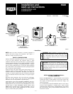
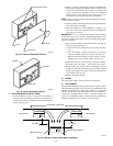
IV. MOUNT THE HUMIDIFIER
1. Attach foam tape to back of mounting flange (exclude the
off-set edge).
2. Hook off-set edge over opening cut in plenum.
3. Place humidifier in plenum aligning screw holes with
flange.
4. Align, level, and tighten all screws for air tight seal.
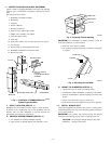
V. INSTALL DRAIN LINE
1. Use 5/8-in. vinyl tubing (field supplied) to connect drain on
bottom of humidifier housing to an open drain.
2. Use clamp to hold drain tubing in position over drain fitting
outlet.
CAUTION: Unit may leak if drain tubing is misapplied.
Do not insert tubing inside of drain fitting outlet.
3. Make sure line is free of traps due to sagging and has
sufficient pitch to drain.
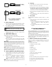
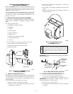
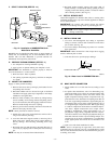
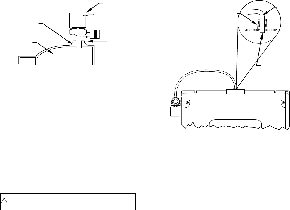
VI. MOUNT SOLENOID VALVE
The water solenoid valve should be mounted on top of humidifier
enclosure.
1. To mount solenoid on top, see Fig. 10.
a. Firmly press valve into the top inlet hole on enclosure.
Seat valve flush against inlet hole.
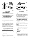
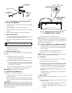
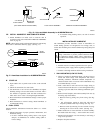
2. If alternate mounting of solenoid is required, see Fig. 11.
a. To mount solenoid on side, use 3/8-in. ID, 1/2-in. OD
vinyl tubing (field supplied). Place tubing onto valve
stem and secure with clamp.
b. Mount valve upside down securing to side of housing.
c. Place open end of tubing into the top inlet hole.
IMPORTANT: Be careful not to kink tubing.
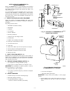
VII. MAKE WATER CONNECTION
If garden hose is not used for water supply:
1. Mount saddle valve on water line according to instructions
supplied with valve.
2. Run 1/4-in. diameter (water line grade) tubing from saddle
valve to adapter on solenoid valve and tighten compression
fittings.
IMPORTANT: If water pressure is higher than normal (60 psi),
use noise suppression disk included in parts bag. (Read water noise
reducer note located inside package for instructions). For normal
operation, saddle valve need only be opened 1 full turn to meet
performance requirements.
3. Open valve and check installation for leaks.
NOTE: Saddle valve is self piercing on copper lines; 1/4-in. hole
must be drilled in steel or iron pipes. Use only a grounded drill or
a hand drill to avoid shock hazard. Turn off water and drain the
pipe prior to drilling 1/4-in. hole.
VIII. INSTALL HUMIDISTAT AND COMPLETE WIRING
1. Mount humidistat on inside wall, or return-air duct in
accordance with section INSTALLATION OF HUMIDIS-
TAT on page 10.
2. Wire red and blue low-voltage leads. (See Fig. 6.)
3. Plug power cord in to 115-vac 60Hz source.
NOTE: Wiring must comply with National Electrical Code and
any local codes or ordinances that may apply.
IX. START-UP
1. Open saddle valve to permit water flow to the solenoid.
2. Check all connections for water leaks.
3. Set thermostat to call for heat. Set humidistat for highest
humidity setting making sure contacts are closed. After a
few minutes of operation, check the drain connection for
leaks and to see if water is flowing through humidifier.
4. Reverse thermostat and humidistat settings to insure proper
shutdown.
5. Reset thermostat to normal setting. Reset humidistat to
recommended setting.
X. FINAL STEPS
Attach humidifier maintenance instruction sticker to a visible
location.
1. Inform homeowner of proper operation, maintenance, and
humidistat setting.
a. If unit is installed during cooling season set humidistat
for summer setting (OFF or lowest setting).
b. If installed during heating season, set unit for normal
operation.
Fig. 10—Top Mounting of Water Solenoid Valve
A97107
SOLENOID
VALVE
HOUSING
ENCLOSURE
INLET HOLE
SEAT
SOLENOID
VALVE
FLUSH
AGAINST
INLET
Fig. 11—Alternate Mounting of Solenoid Valve
on HUMBBSFP1016-A-- Humidifier
A97099
POSITION TUBING
INSIDE INLET HOLE
(CUT LENGTH
IF REQUIRED)
TUBING
ENCLOSURE
INLET HOLE
—6—