—2—
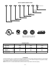
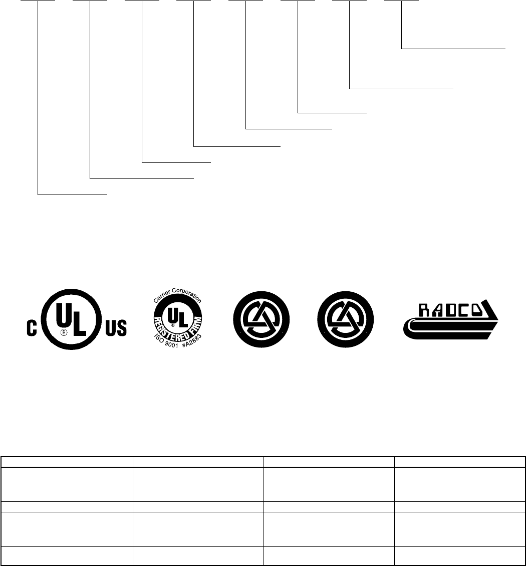
MODEL NUMBER NOMENCLATURE
CERTIFICATION APPLIES ONLY WHEN THE
COMPLETE SYSTEM IS LISTED WITH ARI.
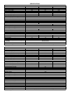
PHYSICAL DATA
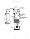
NOTE:
Rough-in dimensions are 38-1/4 x 22-1/4 inches.
CLEARANCES
A minimum clearance of 21 in. is required in front of the access panels for servicing. Please note that this clearance is recommended
for servicing only. Installation clearances from combustible materials are: 0 in. from cabinet and supply-air duct (plenum included).
Leave adequate room for the condensate pan and refrigerant line connection.
NOTE:
22-3/4 to 24-in. on-center between-studs and 38-1/8 to 36-3/4-in. top-to-bottom inside-studs spacing.
F F 1 D N A 018 075
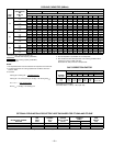
Electric Heater (kw)
000
005
075
011
Nominal Capacity (Btu)
018—18,000
024—24,000
030—30,000
A—Standard
E—TXV
N—208/230-1-60
D—Major Series
1—Upflow
F—Through-the-Wall
F—Fan Coil
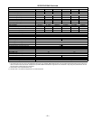
MODEL FF1DNA/FF1DNE 018 024 030
Fan
Rpm (2-Speed)
Motor HP (PSC)
Wheel (In.)
810/750
1/12
10 x 6
980/780
1/5
10 x 6
1110/950
1/3
10 x 6
Filter (Permanent) (In.) 16 x 20 16 x 20 16 x 20
Connections (Sweat)
Suction OD
Liquid OD
Condensate (FPT)
(In.)
(In.)
(In.)
5/8
3/8
3/4
3/4
3/8
3/4
3/4
3/8
3/4
Operating Weight
(With Electric Heat)
(Lb) 76 79 82
M
A
N
U
F
A
C
T
U
R
E
R
C
E
R
T
I
F
I
E
D
T
O
A
R
I
A
S
C
O
M
P
L
Y
I
N
G
W
I
T
H
A
R
I
S
T
A
N
D
A
R
D
2
4
0
U
N
I
T
A
R
Y
H
E
A
T
P
U
M
P
E
Q
U
I
P
M
E
N
T
®
M
A
N
U
F
A
C
T
U
R
E
R
C
E
R
T
I
F
I
E
D
T
O
A
R
I
A
S
C
O
M
P
L
Y
I
N
G
W
I
T
H
A
R
I
S
T
A
N
D
A
R
D
2
1
0
U
N
I
T
A
R
Y
A
I
R
C
O
N
D
I
T
I
O
N
I
N
G
E
Q
U
I
P
M
E
N
T
• CERTIFICATION • LISTING
• TESTING • INSPECTION
®


