


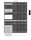
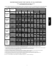
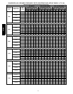
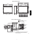

6
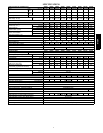
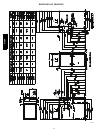
AIR DELIVERY -- CFM (BOTTOM RETURN WITH FILTER)
UNIT
SIZE
RETURN-AIR
CONNECTION
SPEED
TAPS
2
EXTERNAL STATIC PRESSURE (IN. W.C.)
0.1 0.2 0.3 0.4 0.5 0.6 0.7 0.8 0.9 1.0
30040 SIDE/BOTTOM
Black 1100 1055 1010 960 905 850 795 740 685 620
Yellow 955 915 875 830 790 740 695 645 590 530
Blue 820 795 765 730 695 655 615 570 515 460
Red 730 710 680 655 625 595 555 515 465 400
30060 SIDE/BOTTOM
Black 1340 1295 1245 1190 1130 1065 1005 895 815 725
Yellow 1035 1010 980 945 910 865 795 730 665 605
Blue 845 825 810 785 755 710 670 625 570 515
Red
5
770 750 730 710 675 640 600 560 510 455
42060 SIDE/BOTTOM
Black 1665 1615 1550 1485 1420 1345 1270 1190 1105 985
Yellow 1340 1320 1295 1260 1215 1165 1110 1045 925 850
Orange 1050 1045 1035 1015 995 960 915 845 785 725
Blue 985 980 975 950 930 900 845 795 740 690
Red
5
735 720 700 675 650 620 595 560 520 480
48080 SIDE/BOTTOM
Black 1870 1810 1740 1670 1600 1525 1440 1355 1270 1180
Yellow 1525 1495 1460 1415 1365 1305 1240 1170 1090 990
Orange 1375 1355 1330 1300 1260 1210 1155 1090 1025 940
Blue 1045 1040 1030 1010 985 960 920 875 825 745
Red
5
880 865 850 835 810 785 750 715 665 605
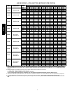
60080
BOTTOM or
TWO-SIDES
3,4
Black 2390 2320 2230 2125 2025 1920 1825 1720 1600 1475
Yellow 2010 1970 1925 1875 1805 1730 1655 1560 1460 1350
Orange 1670 1660 1650 1620 1585 1550 1485 1410 1330 1225
Blue 1500 1500 1495 1485 1460 1425 1380 1320 1255 1165
Red 1270 1260 1255 1245 1225 1195 1160 1125 1065 1000
42100 SIDE/BOTTOM
Black 1780 1735 1685 1625 1565 1495 1415 1325 1240 1145
Blue 1605 1565 1520 1465 1410 1340 1265 1190 1110 1020
Yellow 1345 1310 1270 1225 1175 1120 1060 995 920 835
Orange
5
1130 1090 1045 1000 945 895 840 775 715 635
Red
5
900 855 800 750 695 640 590 525 470 405
60100
BOTTOM or
TWO-SIDES
3,4
Black 2510 2420 2330 2240 2145 2040 1920 1805 1675 1520
Yellow 2030 2010 1970 1925 1870 1805 1725 1630 1525 1400
Orange 1655 1660 1650 1635 1615 1575 1520 1450 1360 1270
Blue 1520 1520 1520 1520 1500 1475 1430 1360 1290 1200
Red 1265 1255 1250 1240 1225 1205 1175 1135 1085 1025
60120
BOTTOM or
TWO-SIDES
3,4
Black 2470 2375 2280 2175 2065 1940 1820 1695 1580 1475
Blue 2275 2210 2125 2045 1945 1835 1715 1605 1500 1395
Yellow 1690 1685 1670 1640 1590 1525 1455 1385 1295 1210
Orange
5
1460 1465 1450 1430 1400 1355 1315 1255 1185 1105
Red
5
1310 1300 1290 1265 1245 1210 1165 1120 1060 985
60140
BOTTOM or
TWO-SIDES
3,4
Black 2485 2395 2300 2200 2100 1985 1865 1750 1635 1520
Blue 2260 2190 2110 2020 1925 1825 1700 1600 1495 1385
Yellow
5
1660 1650 1635 1615 1580 1530 1475 1410 1320 1230
Orange
5
1430 1445 1440 1420 1390 1355 1310 1245 1175 1085
Red
5
1285 1285 1260 1255 1230 1205 1165 1115 1055 975
NOTE:
1. A filter is required for each return---air inlet. Airflow performance includes a 3/4---in. (19 mm) washable filter media such as contained in a factory---author-
ized accessory filter rack. See accessory list. To determine airflow performance with ou t this filter, assume an additional 0.1 in. w.c.. available external static
pressure.
2. Blower speed taps are not always in the same order. Factory default blower connections are as follows:
a. Heating airflow --- BLUE (also used for Continuous Fan)
b. Cooling airflow --- BLACK (enabled when the Y terminal is energized)
ADJUST THE B LOWER SPEED TAPS A S NECESSARY FOR THE P ROPER AIR TEMPERATURE RISE FOR EACH IN STALLATION.
3. Airflows over 1800 CFM require bottom return, two---side return, or bottom and side return. A min imum filter size of 20” x 25” (508 x 635 mm) is r e quired.
4. For upflow applications, air entering from one side into both the side of the furnace and a return air base counts as a side and bottom return.
5. Highlighted areas in dicate that this airflow range is beyond the ran ge allowed for heating. THESE AIRFLOW RANGES MAY ONLY BE USED FOR COOL-
ING.
915SA