


WARNING: Before performing service or maintenance
operations on system, turn off main power to unit and
install lock-out tag. Turn off accessory heater power
switch if applicable. Electrical shock could cause severe
injury or death.
CAUTION: Puron® (R-410A) systems operate at higher
pressures than standard R-22 systems. Do not use R-22
service equipment or components on Puron® (R-410A)
equipment. Ensure service equipment is rated for Puron®
(R-410A)
INTRODUCTION
NOTE: The minimum outdoor cooling operating temperature for
units using this ICM motor option is 55°F. To operate in cooling
at lower ambients the Motor Master™ II low ambient kit is
required.
These instructions cover the installation of a Bryant Small Pack-
aged Product with ICM motor-factory installed option (FIOP).
This option can be selected as a FIOP on gas heating/electric
cooling (583B), dual fuel–electric heat pump with gas heat
back-up (683B), electric cooling (702B) or electric heat pump
(602B) units with Puron®.
RECEIVING AND INSTALLATION
Refer to unit Installation Instructions.
ICM FIOP PRE-START-UP
I. ELECTRICAL CONNECTIONS
A. Control Voltage Connections
NOTE: Do not use any type of power-stealing thermostat, with-
out connecting the C (Common) terminal. Failure to follow this
note could result in unit control problems.
Use no. 18 American Wire Gage (AWG) color-coded, insulated
(35 C minimum) wires to make the control voltage connections
between the thermostat and the unit. If the thermostat is located
more than 100 ft from the unit (as measured along the control
voltage wires), use no. 16 AWG color-coded, insulated (35 C
minimum) wires.
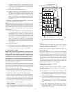
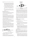
B. Standard Connection
Remove knockout hole located in the heat section panel adjacent to
the service access panel (See unit installation package). Remove
the rubber grommet from the installer’s packet (included with unit)
and install grommet in the knockout opening. Provide a drip loop
before running wire through panel. Run the low-voltage leads from
the thermostat, through the inlet hole, and into unit low-voltage
splice box. Locate 18-gage wires leaving control box. These
low-voltage connection leads can be identified by colors (See Fig.
2, 3, 4 or 5). Ensure the leads are long enough to be routed into the
low-voltage splice box (located below right side of control box).
Route leads through hole in bottom of control box and make
low-voltage connections (See Fig. 2, 3, 4 or 5). Secure all cut
wires, so that they do not interfere with operation of unit.
SPECIAL PROCEDURES FOR 208–V OPERATION
WARNING: Make sure that the power supply to the unit
is switched OFF before making any wiring changes. With
disconnect switch open, move yellow wire from trans-
former (3/16 in.) terminal marked 230 to terminal marked
200. This retaps transformer to primary voltage of 208-v.
Electrical shock could cause serious injury or death.
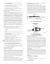
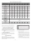
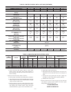
C. Easy Select™—583B
EASY SELECT™ CONFIGURATION TAPS FOR 583B
Easy Select™ taps are used by the installer to configure a system.
The ICM motor uses the selected taps to modify its operation to a
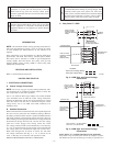
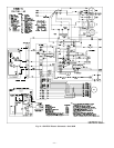
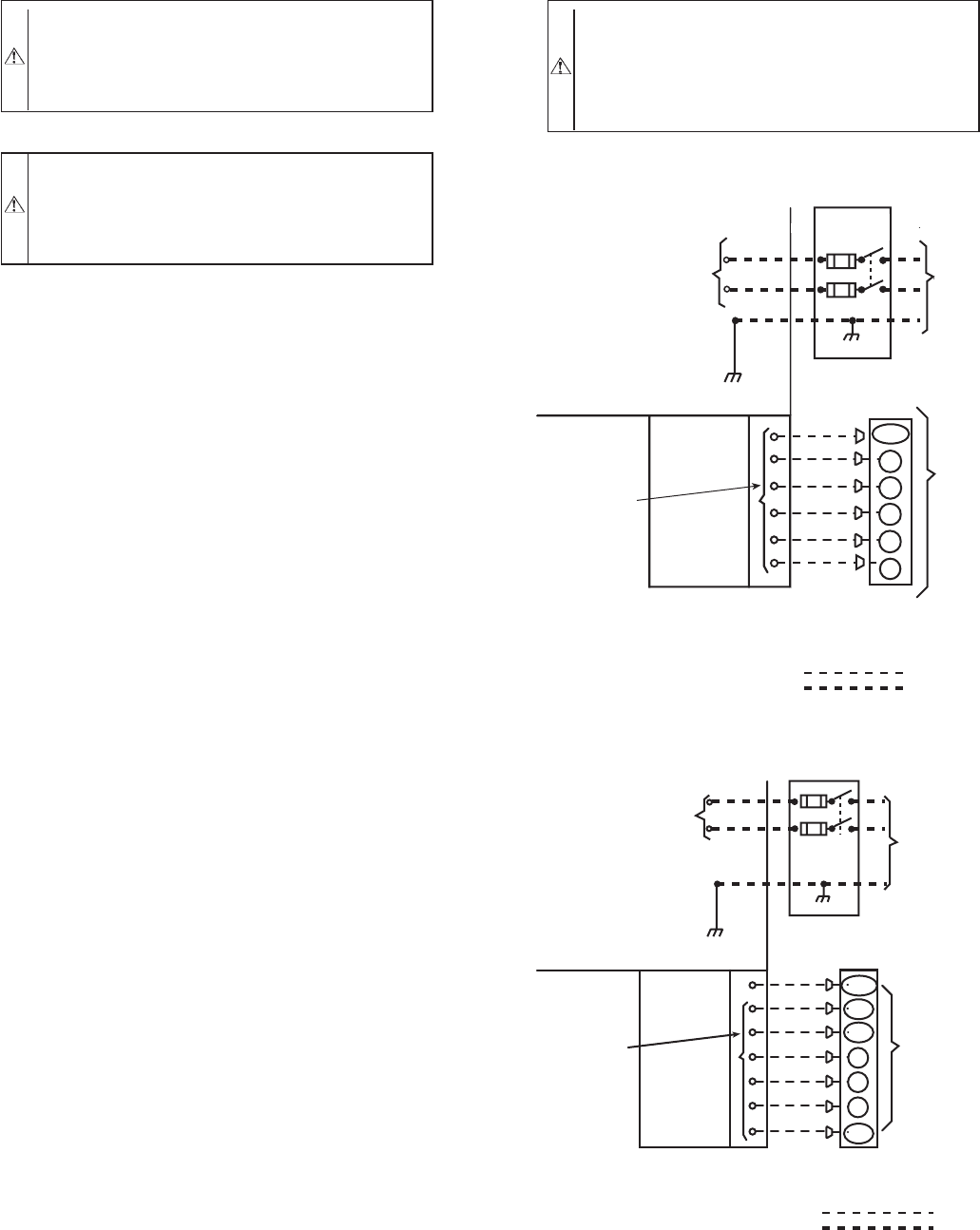
Fig. 2—583B High- and Control-Voltage
Connections
C01026
POWER
SUPPLY
FIELD-SUPPLIED
FUSED DISCONNECT
HIGH VOLTAGE
POWER LEADS
(SEE UNIT WIRING
LABEL)
GND
CONTROL BOX
SPLICE BOX
LOW-VOLTAGE
POWER LEADS
(SEE UNIT
WIRING LABEL)
YEL(Y)
GRN(G)
RED(R)
BRN(C)
THERMOSTAT
(TYPICAL)
LEGEND
Field Control-Voltage Wiring
Field High-Voltage Wiring
BLK(DH)
DHUM
Y
G
R
C
W1
WHI(W1)
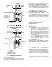
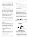
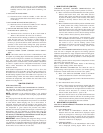
Fig. 3—683B High- and Control-Voltage
Connections
C01107
POWER
SUPPLY
FIELD-SUPPLIED
FUSED DISCONNECT
HIGH VOLTAGE
POWER LEADS
(SEE UNIT WIRING
LABEL)
GND
CONTROL BOX
SPLICE BOX
LOW-VOLTAGE
POWER LEADS
(SEE UNIT
WIRING LABEL)
THERMOSTAT
(THERMIDISTAT ™ )
G
R
C
YEL(Y)
GRN(G)
RED(R)
BRN(C)
ORN(O)
W/W1
WHT(W1)
DHUM
BLK (DH)
FIELD CONTROL - VOLTAGE WIRING
FIELD HIGH - VOLTAGE WIRING
Y/Y2
O/W2
—2—