


blower motor stops. The unit is in a ‘‘standby’’ condition, waiting
for the next ‘‘call for cooling’’ from the room thermostat. The 5
minute compressor delay also applies to heat pump heating mode.
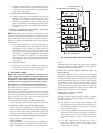
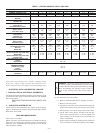
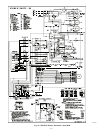
ELECTRICAL DATA & SCHEMATICS—ICM FIOP
I. PHYSICAL DATA & ELECTRICAL SCHEMATICS
Use the Physical Data and Electrical Tables on the following pages
for information that applies to Bryant Puron® units with the ICM
indoor motor FIOP.
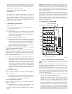
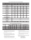
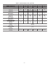
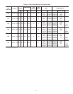
AIRFLOW & TEMPERATURE RISE TABLES—ICM
FIOP
II. TABLES FOR SYSTEM SET-UP
Use the Airflow and Temperature Rise Tables on the following
pages for information that applies to Bryant Puron® units with the
ICM indoor motor FIOP.
CARE AND MAINTENANCE
Indoor Blower and Motor
NOTE: All motors are pre-lubricated. Do not attempt to lubricate
these motors. For longer life, operating economy, and continuing
efficiency, clean accumulated dirt and grease from the blower
wheel and motor annually.
WARNING: Disconnect and tag electrical power to the
unit before cleaning and lubricating any blower motor
and wheel. On units with gas heat, turn off the gas supply
before disconnecting the electrical power. Failure to
adhere to this warning could cause serious injury or
death.
To clean the blower motor and wheel:
1. 1. Remove and disassemble blower assembly as follows:
a. Remove unit access panel.
b. Carefully pivot blower access panel outward towards the
electrical box. Route wiring above blower access panel.
c. Disconnect the 5 and 16 pin plugs at the blower motor.
d. On all units, remove blower assembly from unit. Re-
move screws securing blower to vertical partition and
slide assembly out. Be careful not to tear insulation in
blower compartment.
e. Ensure proper reassembly by marking blower wheel and
motor in relation to blower housing before disassembly.
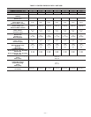
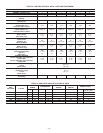
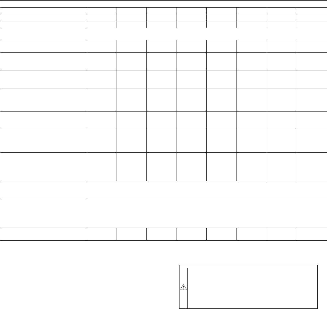
TABLE 1—ICM FIOP PHYSICAL DATA—UNIT 583B
THIS DATA APPLIES TO 583B UNITS WITH THE ICM INDOOR MOTOR FIOP
UNIT SIZE 583B 024040 024060 030040 030060 036060 036090 042060 042090
NOMINAL CAPACITY (ton) 2 2 2-1/2 2-1/2 3 3 3-1/2 3-1/2
OPERATING WEIGHT (lb.) 290 290 313 313 321 321 382 382
COMPRESSORS
Quantity
Scroll
1
REFRIGERANT (R-410A)
Quantity (lb.)
5.0 5.0 5.5 5.5 6.9 6.9 9.0 9.0
REFRIGERANT METERING DEVICE
Orifice ID (in.)
Check-Flo-Rater™ Piston
.057 .057 .057 .057 .065 .065 .070 .070
CONDENSER COIL
Rows...Fins/in.
Face Area (sq ft)
1...17
10.9
1...17
10.9
1...17
12.7
1...17
12.7
2...17
9.1
2...17
9.1
2...17
12.3
2...17
12.3
CONDENSER FAN
Nominal Cfm
Diameter (in.)
Motor HP (Rpm)
2350
22
1/8 (825)
2350
22
1/8 (825)
2350
22
1/8 (825)
2350
22
1/8 (825)
2350
22
1/8 (825)
2350
22
1/8 (825)
2350
22
1/8 (825)
2350
22
1/8 (825)
EVAPORATOR COIL
Rows...Fins/in.
Face Area (sq ft)
3...15
3.7
3...15
3.7
3...15
3.7
3...15
3.7
3...15
3.7
3...15
3.7
3...15
4.7
3...15
4.7
EVAPORATOR BLOWER
Nominal Airflow (Cfm)
Size (in.)
Motor (HP)
800
10X10
1/2
800
10X10
1/2
1000
10X10
1/2
1000
10X10
1/2
1200
11X10
3/4
1200
11X10
3/4
1400
11X10
3/4
1400
11X10
3/4
FURNACE SECTION*
Burner Orifice No. (Qty...Drill Size)
Natural Gas
Burner Orifice No. (Qty...Drill Size)
Propane Gas
2...44
2...50
2...38
2...46
2...44
2...50
2...38
2...46
2...38
2...46
3...38
3...46
2...38
2...46
3...38
3...46
HIGH-PRESSURE SWITCH (psig)
Cutout
Reset (Auto)
610±15
420±25
LOSS-OF-CHARGE/LOW-
PRESSURE SWITCH
(Liquid Line) (psig)
Cutout
Reset (Auto)
20±5
45±10
RETURN-AIR FILTERS (in.)
Throwaway
20X20X1 20X20X1 20X20X1 20X20X1 20X24X1 20X24X1 24X30X1 24X30X1
* Based on altitude of 0 to 2000 ft.
—12—